Hey DIYaudio,
We are looking for some beta testers for our new boards. We have 5 designs are looking for testers for each. We will ship you the boards free of charge, you just tell us how it worked out, was there any room for improvement and send us some photos of it. Below are pictures of the boards. Please PM me if you would like to participate. Space is limited. Let us know! Joe@chipamp
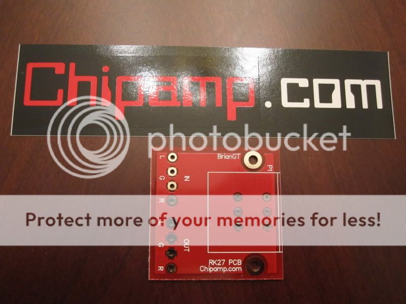
RK27 Board
1. Rodeodave
2. Simon7000
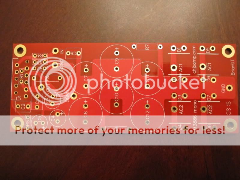
Chipamp 3886 Mono Board
1. syyma
2. imix500
3. benb
4. potepuh
5. Bedi
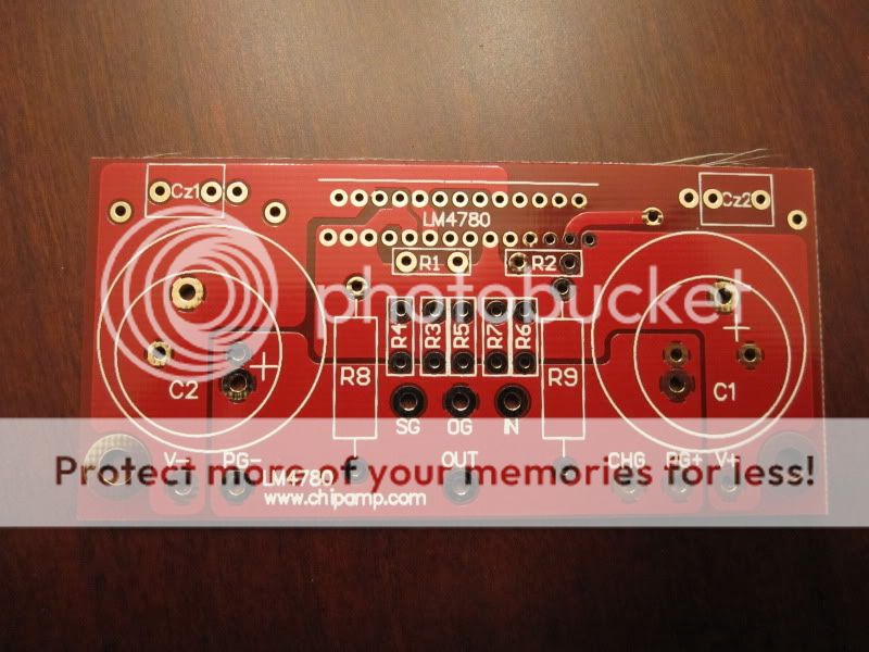
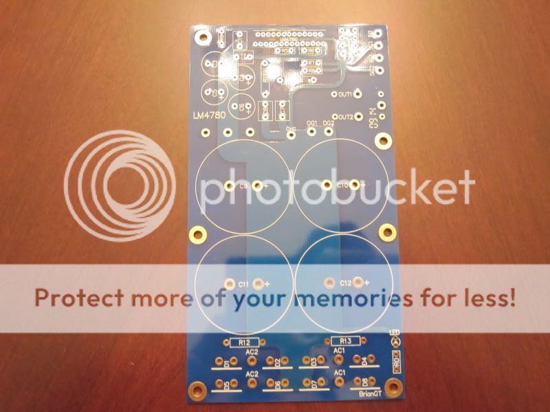
Chipamp 4780 Board (1)
1. Rodeodave
2. Ursv
3. Simon7000
4. potepuh
5. Boscove
Chipamp 4780 Board (2)
1. Rodeodave
2. Ursv
3. DtotheG
4. Boscove
5. Littlerick
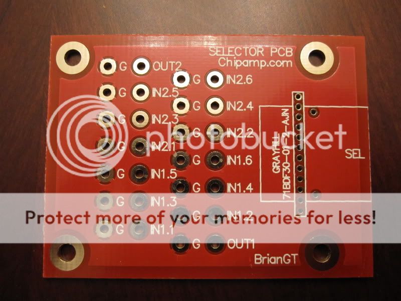
Chipamp Selector Board
1. DtotheG
2. Darpmalone
3.
4.
5.
We are looking for some beta testers for our new boards. We have 5 designs are looking for testers for each. We will ship you the boards free of charge, you just tell us how it worked out, was there any room for improvement and send us some photos of it. Below are pictures of the boards. Please PM me if you would like to participate. Space is limited. Let us know! Joe@chipamp
RK27 Board
1. Rodeodave
2. Simon7000
Chipamp 3886 Mono Board
1. syyma
2. imix500
3. benb
4. potepuh
5. Bedi
Chipamp 4780 Board (1)
1. Rodeodave
2. Ursv
3. Simon7000
4. potepuh
5. Boscove
Chipamp 4780 Board (2)
1. Rodeodave
2. Ursv
3. DtotheG
4. Boscove
5. Littlerick
Chipamp Selector Board
1. DtotheG
2. Darpmalone
3.
4.
5.
Last edited:
What the BOM for this boards? They look pretty simple.
I am having Brian put this together. Should be out soon. -Joe
Last edited:
Same here, the boards look exceptionally well made, can't wait to populate them and fire them up.
RN55D resistors can be used, but the leads have to be bent to make them fit. I can post pictures if wanted.
How do we proceed from here? Should we open a new thread for our builds or do we post our findings here?
RN55D resistors can be used, but the leads have to be bent to make them fit. I can post pictures if wanted.
How do we proceed from here? Should we open a new thread for our builds or do we post our findings here?
Same here, the boards look exceptionally well made, can't wait to populate them and fire them up.
RN55D resistors can be used, but the leads have to be bent to make them fit. I can post pictures if wanted.
How do we proceed from here? Should we open a new thread for our builds or do we post our findings here?
Wow, that made some good time for international shipping. I think i'll make a thread for each board so its neatly organized. I'll try to have that up by the end of the day.
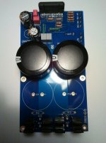
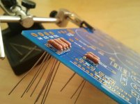
Here's a sneak-peek of my LM4780 stereo build.
Diodes are BYV29-500, big caps are Panasonic TSUP 10000uF 50v, small caps are Nichicon Muse 100uF 50V, small bypass caps are 1uF 63V WIMA. The resistors are CMF55 1% MF, except for the 10k muting resistor which is a compact MF. The values are 15k to GND, 221R to the + input, 20k and 1k in the FB path. The snubber resistor is a 2R7 1W MF resistor, and the snubber caps are 100nF film caps.
Soldering was straight forward, and other than bending the resistors' legs so that they fit, there were no real issues. It's noteworthy that the through-holes of the pcb don't have that bridge/cross type eyelet (don't know the name), so a lot of heat is transferred away from the soldering iron. Thus a fairly strong iron is best, I have a basic 50W Weller and managed to have the solder flow nicely.
I'll likely fire it up tomorrow, we'll see how that goes...
Edit: I have accidentally been sent two selector boards (and unfortunately no RK27 board). I don't plan on using them, so if someone wants to test one (or both) PM me.
Attachments
Last edited:
No, you haven't missed the BOM, it's not out yet. There are some schematics in the datasheet, and countless are floating around in the internet. Since the LM4780 is simply two LM3886s on one chip, I have populated the stereo board with parts/values I have had very good experiences with my earlier LM3886 builds.
Here's a sneak-peek of my LM4780 stereo build.
Diodes are BYV29-500, big caps are Panasonic TSUP 10000uF 50v, small caps are Nichicon Muse 100uF 50V, small bypass caps are 1uF 63V WIMA. The resistors are CMF55 1% MF, except for the 10k muting resistor which is a compact MF. The values are 15k to GND, 221R to the + input, 20k and 1k in the FB path. The snubber resistor is a 2R7 1W MF resistor, and the snubber caps are 100nF film caps.
Soldering was straight forward, and other than bending the resistors' legs so that they fit, there were no real issues. It's noteworthy that the through-holes of the pcb don't have that bridge/cross type eyelet (don't know the name), so a lot of heat is transferred away from the soldering iron. Thus a fairly strong iron is best, I have a basic 50W Weller and managed to have the solder flow nicely.
I'll likely fire it up tomorrow, we'll see how that goes...
Edit: I have accidentally been sent two selector boards (and unfortunately no RK27 board). I don't plan on using them, so if someone wants to test one (or both) PM me.
Looks Great!
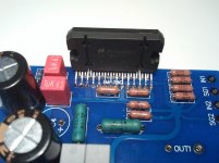
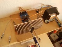
Alright, I just hooked the amp up to my speakers (nothing too special, Dual CL173 3-ways, rated 4 Ohm, rebuilt crossover), and it's sounding marvelous!
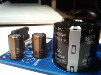
I'm looking forward to adding a second pair of 10mF caps to the PSU, maybe it will have an impact on the already good bass performance, we'll see.
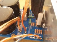
The transformer is a (conservatively rated) 180VA EI-type with dual secondaries, and it puts out 22V AC for each secondary. After rectification and filtering I have pretty much exactly +/-28V DC. The amp is DC coupled for now, and both channels have a DC offset of 60mV, which is perfectly fine.
And yes, that's a clamp holding the chip against the heatsink...
I'm looking forward to adding a second pair of 10mF caps to the PSU, maybe it will have an impact on the already good bass performance, we'll see.
The transformer is a (conservatively rated) 180VA EI-type with dual secondaries, and it puts out 22V AC for each secondary. After rectification and filtering I have pretty much exactly +/-28V DC. The amp is DC coupled for now, and both channels have a DC offset of 60mV, which is perfectly fine.
And yes, that's a clamp holding the chip against the heatsink...
Attachments
- Status
- This old topic is closed. If you want to reopen this topic, contact a moderator using the "Report Post" button.
- Home
- More Vendors...
- Chipamp
- Chipamp.com is looking for Beta Testers