Hi all
I am posting yet again. I am having more problems with my amp
I can get it to work. But only with an i-pod. As soon as I plug in another source it goes badly wrong.
So far I have tried it with my pc, my i-pod and my dac in a box
What is making it go wrong is when the ground from another device is attached. The amp just starts spewing out hums, pops and then cuts out for a few seconds. Then it does the same again ad infinitum
The smps are 4 skynet 8080's rigged to give 24v a la decibel dungeons instructions. I have isolated the smps from ground. However as I see it the ov line in the smps is created only because the smps modules are isolated from earth. When I connect the rca cable the 0v line is no longer floating and my troubles begin.
Am I making sense.
I realise I have probably got something totally wrong, perhaps someone could educate me?
Blair
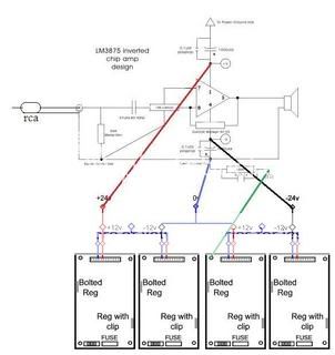
http://i65.photobucket.com/albums/h219/justblair/diagram-1.jpg
I am posting yet again. I am having more problems with my amp
I can get it to work. But only with an i-pod. As soon as I plug in another source it goes badly wrong.
So far I have tried it with my pc, my i-pod and my dac in a box
What is making it go wrong is when the ground from another device is attached. The amp just starts spewing out hums, pops and then cuts out for a few seconds. Then it does the same again ad infinitum
The smps are 4 skynet 8080's rigged to give 24v a la decibel dungeons instructions. I have isolated the smps from ground. However as I see it the ov line in the smps is created only because the smps modules are isolated from earth. When I connect the rca cable the 0v line is no longer floating and my troubles begin.
Am I making sense.
I realise I have probably got something totally wrong, perhaps someone could educate me?
Blair
http://i65.photobucket.com/albums/h219/justblair/diagram-1.jpg
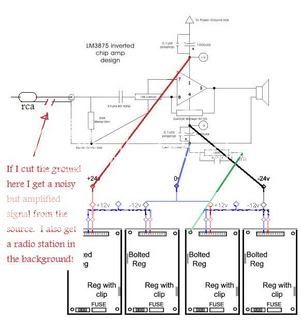
I should have made it clear that I tried cutting the ground on the RCA connector. Then the amp worked with my DAC however I also got loads of noise and interference from a radio station.
http://i65.photobucket.com/albums/h219/justblair/diagram2-1.jpg
http://i65.photobucket.com/albums/h219/justblair/diagram2-1.jpg
I may try going back to the 12v+/- however when I had it running the other night on the ipod it was sounding absolutely glorious, the bass response especially was amazing and detailed. I have two amps per channel wired in a by amp arrangement.
I'm loathed to go back to the lower power.
I am fairly sure I have the amps wired as per the schematics I displayed above.
I'll take suggestions from anyone and their dog to try and avoid having to drop the amps available.
I'm loathed to go back to the lower power.
I am fairly sure I have the amps wired as per the schematics I displayed above.
I'll take suggestions from anyone and their dog to try and avoid having to drop the amps available.
You have it wired wrong. Take a look at this document. It has diagrams of the basic connections for a Gainclone in it.
http://audiosector.com/nigc_kit-users_guide.pdf
Also take a look at this diagram. It looks similar to the one you posted but there are some differences. Where is the referencing resistor to signal ground off the feedback loop on yours? I havent tried to build an inverted Gainclone yet but I hope this info helps.
http://myweb.tiscali.co.uk/nuukspot/decdun/gc/nixgccd2l.gif
Hi G
I have poured over the document that you linked to. My grounding arrangement certainly is not the same as that one. Though I think that it is correct to the schematic. I may have taken the diagram a little too literally.
Looking at the document the 0 lines are connected directly to the amp from the transformers, the signal ground is attached via seperate cables at a single point in the amp. On my amp stages there is a point where the 0v line, a cable to the signal ground, the speaker return and the power caps all meet. Just the way it looks on the diagram.
Is this where you think my problem lies?
I am finding it a bit hard to equate the instructions for smps to the standard instructions. how different are they?
The referencing resistor joins pins 3 and 6 on mine. I am pretty sure that is not the problem. The diagram you linked to is a t networked amp. I dare not even think about making one of those if I can't get this right!
I think I have nothing to lose in trying to run the grounds differently, the fact that it is a ground connection to another device that sends the amp into a tailspin makes me think that.
If anyone else has ten pence worth to chuck in, please do so, It can only help, I am confused enough by the grounding of the amps. I have read all the threads around grounding and the only thing I have learned is that I am not the only one!!!
I have poured over the document that you linked to. My grounding arrangement certainly is not the same as that one. Though I think that it is correct to the schematic. I may have taken the diagram a little too literally.
Looking at the document the 0 lines are connected directly to the amp from the transformers, the signal ground is attached via seperate cables at a single point in the amp. On my amp stages there is a point where the 0v line, a cable to the signal ground, the speaker return and the power caps all meet. Just the way it looks on the diagram.
Is this where you think my problem lies?
I am finding it a bit hard to equate the instructions for smps to the standard instructions. how different are they?
Also take a look at this diagram. It looks similar to the one you posted but there are some differences. Where is the referencing resistor to signal ground off the feedback loop on yours?
The referencing resistor joins pins 3 and 6 on mine. I am pretty sure that is not the problem. The diagram you linked to is a t networked amp. I dare not even think about making one of those if I can't get this right!
I think I have nothing to lose in trying to run the grounds differently, the fact that it is a ground connection to another device that sends the amp into a tailspin makes me think that.
If anyone else has ten pence worth to chuck in, please do so, It can only help, I am confused enough by the grounding of the amps. I have read all the threads around grounding and the only thing I have learned is that I am not the only one!!!
Hi,
Q1, is the amp wrongly wired?
Q2, is the grounding wrongly wired?
Q3, is the smps wrongly wired?
Q4, is the SMPS interacting with the amplifier?
We don't know until you dump the smps and temporarily fit a conventional transformer+rectifier+smoothing caps.
Then we should find if the fault is in the SMPS or in the rest of the arrangement.
I think I can answer the questions. I got it working on a soundcard. One channel so far.
I moved my bypass filter onto a piece of wire, leading from the power ground to earth. previously it tied the 0v line to earth further down the chain.
It tells me one of three things were wrong.
1. The filter was faulty, I perhaps damaged the cap at some point.
2. The wiring was wrong.
3. Having 4 amps running through one filter was overloading it.
It was a bit of a guess trying it, I read the document that G sent to me and sort of cludged the idea from there. I dont personally understand why tying the 0v to earth through a seperate cable should make a difference?
The other thing that I did was to add a 10ohm load to the 5v line of the smps but I dont think that has anything to do with it.
Part of me wants to experiment to get to the reasoning behind it, part of me wants to leave well enough alone. I hate the fact I lost the DAC. Even if I am pretty sure I can fix it, I was looking forward to hearing it. I looked inside and the new dac in a box looks quite a bit better than the old inside.
On a lot of GCs I have seen people just float the circuit. By that I mean that they use a safety ground to the chassis but the do not earth the signal ground. Have you checked to make sure that each individual SMPS module is putting out exactly the same voltage? I suspect that the problems are being caused by the SMPS modules and not the circuit. I wish I could be more helpful but my experience with chip amps is not very broad. I am more of a tube guy. I have recently put together the parts for a GC because I wanted to see what all of the fuss is about. Let us know if you have any luck.
The other thing that I did was to add a 10ohm load to the 5v line of the smps but I dont think that has anything to do with it.
Do you mean you changed from another value to 10R, or didn't use any load resistor before?
As a rule, if you have a ground problem you will get a constant noise, hum, buzzing etc. Intermittent noise usually indicates a bad connection or a faulty component.

G said:On a lot of GCs I have seen people just float the circuit. By that I mean that they use a safety ground to the chassis but the do not earth the signal ground. Have you checked to make sure that each individual SMPS module is putting out exactly the same voltage? I suspect that the problems are being caused by the SMPS modules and not the circuit. I wish I could be more helpful but my experience with chip amps is not very broad. I am more of a tube guy. I have recently put together the parts for a GC because I wanted to see what all of the fuss is about. Let us know if you have any luck.
The SMPS arrangement is working just fine. I'm getting +/-24.7v under load off of each output. I suspect that SMPS is not as complicated as I think it is, just not that many folks here use it so newb advice is only available from NUUK (Who of course has been very helpfull)
I see you mention you have the parts. I would be interested in how you compare them. My flatmate has a few cheap berihnger pentodes going spare that he has swapped out of a mic preamp. But I think I have some learning to do before I attempt to use them.
G said:On a side note Blair I just tried some single malt Scotch a week ago and loved it. I think it was called Abelour. What brand do you like? Of course I'm assuming that everyone in Scotland drinks scotch.
I favour a Laphroaig personally, Its a lovely island malt, soft and peaty. Beautifull on its own, and also very refreshing if mixed with lemonade

Nuuk said:
Do you mean you changed from another value to 10R, or didn't use any load resistor before?
As a rule, if you have a ground problem you will get a constant noise, hum, buzzing etc. Intermittent noise usually indicates a bad connection or a faulty component.
I didn't have the 10r's connected before, or to be honest I had forgotten to refit them when I moved the Skynets into the case.
I cant really say I noticed a difference without them, but then I have been struggliing so far with this grounding issue
The issue I think is most certainly grounding. The problem was not intermittent, It was constant as long as a source with its own fixed ground was plugged in. The I-pod worked because it shared an earth with the amp.
My best bet is that the 100R .22uf filter that connected to ground earth has become damaged. Its the only component that I have replaced. The resistor on it is fine, I can measure that, but my (now overworked) multimeter cant measure capacitance so I cant say for sure without a bit more effort. It may just have been a dodgy cap in the first place or I may have inervertantly overloaded it at some point.
Now I am going to have another stab at the discrete buffer. See if I can't get it running.
Thanks Everyone for suggestions, sometimes I just get to the point where I think I have tried everything, some experianced guidance got me back on track and back to basics.
Hi,
the disconnecting network consisting of C//R whether faulty or intact will have virtually no effect on the described problem.
The disconnecting network between safety earth and audio ground can be either R or R//C or C or shorting link and to varying extents all work.
I wonder if there is a voltage and consequential current being imposed on the ground line by one or more components.
One component can tolerate this voltage difference but the others carry the excess ground line current generating an intolerable voltage that causes the problem to surface.
Could a temporary set of 1r0 resistors be put into every ground line? Then voltage measurements taken across each resistor and comparisons between the well-behaved system readings against the problem readings might reveal a clue.
What happens to the SMPS voltage if a dummy 8r0 load is placed across each 24Vdc supply in turn (measure both the loaded and unloaded SMPS and measure the 0V line in between each dual SMPS)? Probably best to disconnect the amps before doing this.
justblair said:I see you mention you have the parts. I would be interested in how you compare them. My flatmate has a few cheap berihnger pentodes going spare that he has swapped out of a mic preamp. But I think I have some learning to do before I attempt to use them.
Nonsense. If I can build a tube amplier from scratch anyone can. I'm using a single ended EL34 amplifier with a E182CC as the input valve. Good quality transformers are the key to a good tube amplifier.
justblair said:I favour a Laphroaig personally, Its a lovely island malt, soft and peaty. Beautifull on its own, and also very refreshing if mixed with lemonade
I picked up a bottle of Macallan 12 year old last night. I'll try the Laphroaig next. Good scotch is expensive is it not?
justblair said:The issue I think is most certainly grounding. The problem was not intermittent, It was constant as long as a source with its own fixed ground was plugged in. The I-pod worked because it shared an earth with the amp.
I'm confused here. Is the power circuit in your home grounded? Any component you plug in should share the same earth ground. Have you checked for a cold solder joint? I know these may seem to be trivial questions but sometimes the devil is definately in the details.
One of my chips just died.
The problem went away!
Not till after I had fried several more of the 100r/.22uf filters. The resitors were glowing red
I now have 3 perfect power amps and one very dead one.
The broken chip I measured Its spewing out +24 into the output and the ground line to it is reading -24. I think that it may have been messing everything up as it was in the process of dying. I checked my circuit and there was nothing wrong with it, everything was wired as it should be
Still 1 lm3875 is way cheaper than the dac that bought it the other night.
I feel like a nightmare is over! I feel kinda relieved as well, cause it appears that I'm not just as dumb as I was begining to feel.
The amp is sounding very very good, even with the 3. Onto the internet to order a few more chips. First I need a parts list for the broken DAC. Expect to see another thread in the digital section!
Thanks to all who tried to help.
- Status
- This old topic is closed. If you want to reopen this topic, contact a moderator using the "Report Post" button.
- Home
- Amplifiers
- Chip Amps
- LM3875 SMPS problem pretty sure its my grounding arrangement