I tried gainclone with gain=1, and it got pretty hot in a very short time. I think, according to the others' comment in this thread, it is due to an oscillation. I tried both T and TF package, and both of them got hot. Actually, I was thinking to use a gainclone as a power amp without any gain, but it doesn't seem to be possible because of the nasty oscillation.
What I'm thinking right now is that if I set the gain of gainclone to, say, 20 and put a voltage divider at the input before the coupling cap, and hook it up to a tube preamp with a maximum gain of 20 dB, would it be worth trying? As I heard, the main benifit of using tube amps is at the voltage amplification. In the configuration stated above, voltage amplification is done first at the tube stage, and signal gets lower by the voltage divider, and then voltage is amplified again by gainclone. In such a case, there wouldn't be any benifit of using a tube line stage, IMO.
I would like to know what others think about this configuration. Is it gonna be worth trying or a waste of time and money?
Thanks in advance.
Yes, I realized why the gain less than 10 is not recommended by NS. Definitely it doesn't seem to be a good idea to run the amp with such a low gain though I cannot hear the oscillation. It should also be applied to non-inverting configuration, right? I gotta try it.
Mmmm, then I'll have to think about which power amplifier, which is simple to build, will go well with tube preamp. Another tedious search is about to begin now. Any recommendation, please?
Mmmm, then I'll have to think about which power amplifier, which is simple to build, will go well with tube preamp. Another tedious search is about to begin now.
Any recommendation, please?Hi,
Then you did badly wrong. Big booboo. You CANNOT get unity gain in non-inverting topology, you can extremely easily get unity gain in inverting mode. Simply use a pair of 220k Resistors, one from the Amp input to the inverting input, the other from the inverting input to the Output.
NOW observe the magic. Place a 22k resistor between the inverting input and ground. Then place an 18k resistor between the positive input and ground. Unity gain and stable. Easy as pie.
Sayonara
PS, this same sort trick lets you use the OPA637 as I/V converter without osccillation. It sounds notably better than OPA627 in this position but is not unity gain stable....
I tried gainclone with gain=1, and it got pretty hot in a very short time.
Then you did badly wrong. Big booboo. You CANNOT get unity gain in non-inverting topology, you can extremely easily get unity gain in inverting mode. Simply use a pair of 220k Resistors, one from the Amp input to the inverting input, the other from the inverting input to the Output.
NOW observe the magic. Place a 22k resistor between the inverting input and ground. Then place an 18k resistor between the positive input and ground. Unity gain and stable. Easy as pie.
Sayonara
PS, this same sort trick lets you use the OPA637 as I/V converter without osccillation. It sounds notably better than OPA627 in this position but is not unity gain stable....
I used all 47k resistors. Let me see what I did wrong... I think I didn't use one resistor which is 22k in your recommendation. I directly connected the signal to a resistor which is connected to the inverting input. I thought the one (22k in yours) was not necessary because inverting input could be thought as a virtual ground. Wrong? Sorry for my poor knowledge, but I thought I had read it somewhere. Do you think putting that resistor will make a difference? Please let me know, Sayonara Sang. 
Maybe this is motor boating...
Kuei Yang Wang,
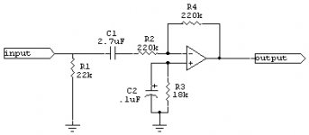
Is the attached circuit as you described? I have a really bad hum now. For C1, I used 2.7uF because I didn't have 2.2uF. It shouldn't matter, I guess. I also tried changing R3 to 220k. No difference. Could you (or anybody) tell me what is wrong? Of course, I used a star ground.
Thanks.
Kuei Yang Wang,
Is the attached circuit as you described? I have a really bad hum now. For C1, I used 2.7uF because I didn't have 2.2uF. It shouldn't matter, I guess. I also tried changing R3 to 220k. No difference. Could you (or anybody) tell me what is wrong? Of course, I used a star ground.
Thanks.
Attachments
Hi,
Wrong. It's there to provide a noise gain of slightly over 10, ensuring the amp is stable.
Sayonara
If i may volunteer a reply the 22k resistor is there to provide stable dc reference.
Wrong. It's there to provide a noise gain of slightly over 10, ensuring the amp is stable.
Sayonara
Re: Maybe this is motor boating...
Hi,
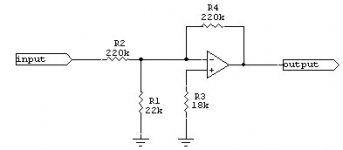
No, of course not. The 22k Resistor goes on the Power Op-Amp Chip's INVERTING INPUT, as I wrote. NOT on the Amplifier input.
Also, I'd think you could in most cases ditch the input coupling capacitor, if you need it, try 0.1uF Foil/Film.
You did not wire as direccted in my original post, reading:
"Place a 22k resistor between the inverting input and ground."
Sayonara
Hi,
Is the attached circuit as you described?
No, of course not. The 22k Resistor goes on the Power Op-Amp Chip's INVERTING INPUT, as I wrote. NOT on the Amplifier input.
Also, I'd think you could in most cases ditch the input coupling capacitor, if you need it, try 0.1uF Foil/Film.
Could you (or anybody) tell me what is wrong?
You did not wire as direccted in my original post, reading:
"Place a 22k resistor between the inverting input and ground."
Sayonara
Attachments
JAZZ' idea of a voltage divider may not be as silly as it sounds from a first view.
If you make this happening only at high frequencies, where also the oscillation usually takes place (BTW: has anybody an idea about the frequency range ?), then you won't affect audible noise and you have an additional input slew-rate/RF pickup reduction.
I don't have any of these ICs on hand but if someone is experimenting with these anyway it won't take much time to try it out.
One simply splits the input resistor in two different sized parts, for instance with a ratio of 1:3. The smaller one being closer to the inverting input. From the node between the two resistors you connect a capacitor to ground forming a lowpass with
fc=1/(2*Pi*C* R1a//R1b).
The upper cutoff frequency should be chosen well out of the audio range.
Just my two pence.
Regards
Charles
No gain, No Pain...
Thanks to Kuei Yang Wang, prototype gainclone with unity gain is finally working. The chip doesn't get hot at all. Like he wrote, it's almost magic to me. I'll order some quality resistors and make a real version of it.
BTW, I would guess that the 18k resistor is for impedance matching for both inverting and non-inverting inputs. The impedance seen by non-inverting input is 220k//220k//22k which equals to ~18k. So, I can understand how it comes up with that value. But, what is the role of 22k resistor?
If I want to set the input impedance to 47k, should I replace 22k with 4.7k and 18k with 3.9k (or with the closest standard value)?
Re: No gain, No Pain...
Hi,
To make the Amp think it has a gain of 10 and thus to stop oscillating.
Yes.
Sayonara
Hi,
But, what is the role of 22k resistor?
To make the Amp think it has a gain of 10 and thus to stop oscillating.
If I want to set the input impedance to 47k, should I replace 22k with 4.7k and 18k with 3.9k (or with the closest standard value)?
Yes.
Sayonara
I first built the original inverted Thorsten schematic, and had some hum and noise (especially when volume was 0 or max); now I've changed it like Kuei suggests (pic). And also, as was predicted, it's now 'dead quiet'. 0 hum and 0 noise.
's wonderful..

- Home
- Amplifiers
- Chip Amps
- Gainclone...No gain, YES pain.