My BrianGT-sourced Gainclone kit is nearing readiness to light up. However, I'm a little concerned about what happens to those 1000uf caps if I power down and they're not discharged.
For instance, I'd like to turn on the PSU and measure the voltage, you know, to make sure I don't fry the whole thing on the first try in case I did soemthing wrong. However, without a load connected, the PSU caps would still be charged, no?
I've read about people using bleeder resistors that are wired in, as well as various gizmos that can drain a cap safely using LEDs and resistors, or light bulbs. However, I am not sure how to size these pieces.
A) Is my concern unnecessary in this particular case?
B) If not, then what have other people used for this purpose?
I'd love to power up and make some noise tonight, but I'd prefer that noise not involve me hitting the floor. That's more bass than I need.
 .
.A bleeder could ba a 5W power resistor of different values ex 6Kohm, that you connect "over" the caps, easiest is to connect it to
p+ and pg+ and another to p- and pg-
That is, between positive supply and positive gnd,and negative supply and negative gnd.
Then you can just measure that the voltage is dropping to see that it's working
p+ and pg+ and another to p- and pg-
That is, between positive supply and positive gnd,and negative supply and negative gnd.
Then you can just measure that the voltage is dropping to see that it's working
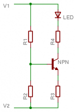
Seeing as this is a good topic, I'll share one of my favorite methods. The circuit is attached. It can be used from rail to ground or rail to rail. Part values need to be selected based on system voltages, desired current draw, and allowable power dissipation.
The circuit is meant to draw a fixed amount of current (assuming a fixed voltage between V1 and V2) through the LED regardless of what LED is used. You could even use a string of LEDs as long as their total voltage drop is less than the voltage between V1 and the emitter of the transistor. This is good for LEDs since their intensity is a function of the current drawn through them and not the voltage across them. The LED doesn't even need to be there but is a nice touch if you like visual confirmation when voltage is present.
Here's a quick example. Assume this will be used on a gainclone amp with +/-30V rails. I would opt to use one circuit per rail so that the caps on each rail are discharged separately. This means V1=30V and V2=0V. A readily available transistor like the 2N3904 would be fine for this purpose. Now, say we want about 5mA flowing through the LED. I usually set R1=R2 for simplicity, so that means there will be 15V at the base of the transistor and about 14.3V at the emitter. For 5mA of emitter current R3=14.3/0.005=2860ohms. Any readily available value close to this will do. Let's use 2.8kohm. Now calculate the resistor dissipation to make sure it won't burn up. Pdissipation=(0.005)(0.005)(2800)=0.07W. Even small 0603 chip resistors can handle that kind of dissipation. Since we're already using a 2.8kohm resistor, we may as well see if they'll work for R1 and R2. 30V across 2*2.8kohm means about 5.4mA will flow through each resistor. Pdissipation=(0.0054)(0.0054)(2800)=0.082W. Still capable of being dissipated by tiny 0603 chip resistors.
Let's check the dissipation in the transistor to see if we even need to use R4. We can assume a worst case voltage of about 30-14.3=15.7V across the transistor. With an LED in series with the collector there will be a couple to a few volts less depending on what type and color LED is used. Pdissipation=(15.7)(0.005)=0.0785W. Well within the limit of the 2N3904 so R4 is not needed.
Now we have determined that 30V across the circuit using R1=R2=R3=2.8kohms will draw a constant 5mA of current through the LED and about 5.4mA through R1 and R2 for a total current draw of about 10mA (at 30V). As the rail voltage collapses the circuit will draw less and less current as the base voltage drops and the LED will eventually turn off. R1 and R2 will continue to discharge the caps when current stops flowing through the LED.
If your amp incorporates some sort of turn off circuit that requires a turn on signal this circuit can be used for that too. Simply make the resistors appropriate values that will give you the desired voltage at the emitter of the transistor. When the power rail comes up so will the emitter voltage. As the power rail drops so will the emitter voltage. This is an easy way to incorporate a status LED, turn on/off signal, and rail discharging with one simple circuit.
Alternatively, a zener diode could be used instead of R2 for more constant current draw over a larger voltage range, but resistors are cheaper than zeners.
Attachments
The amp chip will drain the charge off the caps, so it really isn't necessary to have a bleeder unless the power supply is in a separate enclosure from the amp. In that case, the supply may get switched on without a load so providing a means to bleed off the charge is a good idea.
A simple resistor wired across the rails works fine. All the math you need is the power law:
power dissipated by the resistor = voltage^2/R
Let's say you don't have anything by 1/4 watt resistors handy and let's say your amp runs on +/- 25V (that's 50V rail to rail).
0.25W=50^2/R gives R= 10,000 Ohms. As long as R>10k, the resistor will dissipate <0.25W
Let's say you have a 2k Ohm, 2W resistor laying around. Can you use it?
2W=50^2/R gives R=1250 Ohms. Since 2k>1250, you can use the resistor and know that it will dissipate less than its rated 2W.
I_F
sansbury said:My BrianGT-sourced Gainclone kit is nearing readiness to light up. However, I'm a little concerned about what happens to those 1000uf caps if I power down and they're not discharged.
Mayday said:A bleeder could ba a 5W power resistor of different values ex 6Kohm, that you connect "over" the caps, easiest is to connect it to
p+ and pg+ and another to p- and pg-
Greetings.
What BrianGT-sourced Gainclone kit do you have? The more recent LM3886 kits have a bleeder on PSU boards.
Attachments
http://www.diyaudio.com/forums/showthread.php?s=&threadid=78766&highlight=
Size your bleeder resistors properly if you want to. I looked this up for a friend to show him my spreadsheet with all the maths done for you... and your post came up. I hope this may help anyone who has the same question (I did).
Size your bleeder resistors properly if you want to. I looked this up for a friend to show him my spreadsheet with all the maths done for you... and your post came up. I hope this may help anyone who has the same question (I did).
- Status
- This old topic is closed. If you want to reopen this topic, contact a moderator using the "Report Post" button.
- Home
- Amplifiers
- Chip Amps
- gainclone PSU- how to safely discharge caps?