Hi there,
I just built an amplifier with 2 lm3886's. I am just a hobbiest, and haven't worked on stuff like this for 10 years or more. I had an old power amp that was blown up with a good power supply and I thought I would give it a try. Worked out really well. I now have a power amp with a switch, 1 input, 1 output and volume pot that I guess runs about 100 watts for ~$10.00 and sounds fine. The only the feature the amp doesn't have that I think would be really nice is some kind of led meter to indicate when the amp is being driven too hard. These seems standard on most power amps. Now, I have searched and seen led meters etc talked about, but to be honest, they are more complicated than my amp! (which is more or less the 3 resistor version). Is there something simple like a zener diode with a resistor and led that I can setup just to run like a clip indicator. I mean, I think I'll hear the amp clipping, but I just think it seems standard to have such a feature.
In short, I would like an LED that is off when the signal going into the amp is below a certain threshhold, and on when the signal is above a threshold.
I also am hoping to find something passive that doesn't require me to power an op amp or something, and hopefully only has a few parts.
Thank you for helping with this question, sorry if it is so novice.
I really would be proud if the amp was kept ultra simple.
Simple 1 LED volume meter, please critique
I see what you mean, but I think they can be very useful under certain situations. For example, if you are running a mixing board into a compressor into and eq into an amp and you are hearing clipping, you would like to be able to glance at the equipment and see what is being driven too hard. Also if you are in a room with 500 people and your amp is 50 ft away, and are not sure how much headroom you have left to drive the amp, this could be useful. But I agree, use your ears, not your eyes.
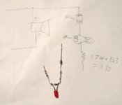
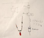
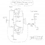
I came up with a circuit, and any critique by anyone would be appreciated. I first started with a parrallel circuit at the speaker output. I first knocked the voltage down with a resistor. I put a regular silicone diode to only allow current 1 way. This feeds into a zener diode in reverse, which in a perfect world would not conduct at all until a threshold is reached and then would conduct at a constant voltage drop. The LED is placed across the zener diode, which I used a 2.4 volt. I adjusted a potentiometer to get the light to come on when the amp is being driven at the maximum power I want. The resistor ended up being 3.3k.
Here is a picture of the circuit:
The parts are: 3.3 k resistor, 2.4 volt zener diode, !N4007 silicone diode, and LED.
For as simple as it is, it works ok. The zener diode leaks and lets through some faint light when them amp is not clipping, but with large peaks it comes on brightly.
Any critique suggestions would be helpful.
I see what you mean, but I think they can be very useful under certain situations. For example, if you are running a mixing board into a compressor into and eq into an amp and you are hearing clipping, you would like to be able to glance at the equipment and see what is being driven too hard. Also if you are in a room with 500 people and your amp is 50 ft away, and are not sure how much headroom you have left to drive the amp, this could be useful. But I agree, use your ears, not your eyes.
I came up with a circuit, and any critique by anyone would be appreciated. I first started with a parrallel circuit at the speaker output. I first knocked the voltage down with a resistor. I put a regular silicone diode to only allow current 1 way. This feeds into a zener diode in reverse, which in a perfect world would not conduct at all until a threshold is reached and then would conduct at a constant voltage drop. The LED is placed across the zener diode, which I used a 2.4 volt. I adjusted a potentiometer to get the light to come on when the amp is being driven at the maximum power I want. The resistor ended up being 3.3k.
Here is a picture of the circuit:
An externally hosted image should be here but it was not working when we last tested it.
The parts are: 3.3 k resistor, 2.4 volt zener diode, !N4007 silicone diode, and LED.
For as simple as it is, it works ok. The zener diode leaks and lets through some faint light when them amp is not clipping, but with large peaks it comes on brightly.
Any critique suggestions would be helpful.
Attachments
What you really want here is a comparator that compares the output voltage from the amp to a clipping reference voltage set by a trim pot. It should also have some circuit to keep the LED lit for maybe 100 ms so that you will actually see it even if the clipping is a very short peak. You can use a 555 timer wired as a monostable (aka one-shot) for that.
If the waveform isn't symmetrical, or the amp isn't, it may clip one rail before the other so you may want to set up two references and use a "window" comparator.
A window comparator's output is high when the voltage input is within the set range, and it goes low when the voltage goes outside that range (such as when clipping either the positive or negative rails). The low output can be used directly to trigger a 555 monostable that drives the LED.
I_F
Right now I am experimenting with 2 more circuits and I will place a post after I finish. The first is a circuit using the "transistor as a switch" concept to turn on the led. The second circuit is more basic, but I think it might work. I have a dual led, red one way, green the other. I am seeing if I can get something cool to work that way. The 555 timer is top of the line, but I am going to try some simpler things first. I will post what I find out soon. Thanks, Gary
impsick said:this is interesting. i need a clip light also for a mic pre im building. any schematics of this circuit?
Look up "window comparator" and look up "555 monostable". Connect the two and you have a clipping indicator.
If you can program uCs, a chip with an A/D converter can be programmed for the same function. The comparator and one-shot can be implemented in software.
I_F
Re: led schematic
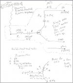
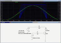
This circuit won't work well. The cap won't do anything for you except maybe act as a high pass filter whose corner freq will vary considerably depending on the base resistor value. You're relying on the Ib to work with the base resistor to divide the voltage. The problem is that Ib varies all over the place. You need a resistor from base to ground to divide the voltage instead of relying on Ib.
Here is your circuit minus the cap. I stepped the base resistance so you can see how sensitive the turn-on point will be to the resistance value. Notice that the current through the LED (blue) starts to look like the voltage curve which says your transistor is not acting as a switch.
garydmd said:"transistor as a switch"
This circuit won't work well. The cap won't do anything for you except maybe act as a high pass filter whose corner freq will vary considerably depending on the base resistor value. You're relying on the Ib to work with the base resistor to divide the voltage. The problem is that Ib varies all over the place. You need a resistor from base to ground to divide the voltage instead of relying on Ib.
Here is your circuit minus the cap. I stepped the base resistance so you can see how sensitive the turn-on point will be to the resistance value. Notice that the current through the LED (blue) starts to look like the voltage curve which says your transistor is not acting as a switch.
Attachments
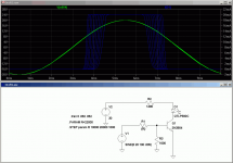
The problem is, Vbe varies a lot with temperature and this simple circuit has no scheme to correct for it.
Here I fixed the base input resistor and stepped temperature from 10 - 50C, a reasonable range inside your amplifier box...
You can see that the threshold voltage varies a lot over that relatively narrow temperature range.
Note that the LED is on for only about 1 ms though this is only a 100 Hz signal that is triggering the circuit. Higher frequency transients that cause the amp to clip will result in even shorter duration flashes which may not be easy to see because of the low current driving the LED. You could crank the LED current up to maybe 300 mA, but then you'll burn it up if the circuit is ever triggered to turn the LED on for more than 50 ms or so. It will probably flash repeatedly in actual operation, but unless you're overdriving the amp hard, the duty cycle will be low and it will appear dim. This is why I suggested a monostable to drive the LED.
Attachments
thank you
Thank you for looking at this circuit. You have been a great help. I am going to add the resistor and pull the capacitor like you said. I think that will work much better. When I get a final circuit done, I will post a graph of LED current vs. input voltage for several freqencies. I will not be able to work on it for a few days but I will post it as soon as I get it running. And I want to thank you for your expertise again in my quest to build the simplest 1 led audio meter.
Thank you for looking at this circuit. You have been a great help. I am going to add the resistor and pull the capacitor like you said. I think that will work much better. When I get a final circuit done, I will post a graph of LED current vs. input voltage for several freqencies. I will not be able to work on it for a few days but I will post it as soon as I get it running. And I want to thank you for your expertise again in my quest to build the simplest 1 led audio meter.
It may be a bit more complex, but there are kists out there:
clipping indicator
Sound impairment monitor
clipping indicator
Sound impairment monitor
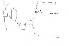
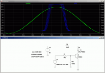
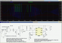
Here's one that detects positive voltage at the output. The stuff on the left generates a variable voltage/frequency input signal (that's your amplifier). Resistive divider divides the voltage swing within the range of +/-5V. A trim pot on the + input of the comparator sets the LED trigger voltage. You need to check your amp specs and see what the clipping voltage will be, then set this point to fire the LED at some voltage below that level.
The 555 drives the LED for however long you want at the onset of clipping. I used a short time constant here- a practical circuit would use maybe 10X what I used here (use 1000nF instead of 100nF for C1).
Don't forget to use a blue LED for best sound!")
The 555 drives the LED for however long you want at the onset of clipping. I used a short time constant here- a practical circuit would use maybe 10X what I used here (use 1000nF instead of 100nF for C1).
Don't forget to use a blue LED for best sound!
Attachments
- Status
- This old topic is closed. If you want to reopen this topic, contact a moderator using the "Report Post" button.
- Home
- Amplifiers
- Chip Amps
- please help newbie clip LED passive