LM4780 is a dual LM3886 in a single substrate
National does not give any information about the matching of both channel in the datasheet. May I know how well can I expect the channel matching from single LM4780 compared to two LM3886? I am looking into building parallel chipamp.
the 2*3886s in a single substrate would be matched in many ways , eg. beta, power o/p, etc as both chip set are made from a single substrate, an analogy is twins born from the same mother.
If you want to parallel them the external components must also be matched such as the resistors. Go to this site: http://www.tech-diy.com
It gives all the details.
I come from Malaysia as well.
cheers..
If you want to parallel them the external components must also be matched such as the resistors. Go to this site: http://www.tech-diy.com
It gives all the details.
I come from Malaysia as well.
cheers..
I assume as it is logical, rather than 2 separate die and bring together and put them in one chip. Even if they are made separately they are from the same production run, their electrical parameters must be very close much closer than discrete components.
I maybe wrong if you want to pursue this further ask national.
I maybe wrong if you want to pursue this further ask national.
")
In response to using two LM3886 or an LM4780 chipamp with outputs wired in parallel :
Hi
it seems that this forum is one of thew main contact point for chipamp freaks, maybee u can help me here.
I've just built a3886 based Amp for a friend and it worked pretty well.
Now i'd like to build one of these for my computer.
I have very big speakers, with 12inch woofers, 4Ohm, and I want to use a 2x22V Transformer.
This seems to be a little hard for a single 3886.
Now im thinking about paralleling two LM3886 or one 4780 will give more reserves.
Is this going to destroy the sound of the gainclone?
Yes, there are hundreds of threads, but I found no answer for this point...
Regarding the parallel operation of two LM3886's or one LM4780 chip-amps: The answer is YES, YOU CAN DO THIS and NO, IT WILL NOT NEGATIVELY IMPACT THE SOUND OF YOUR SYSTEM. This configuration is good down to about 2.7 ohm load per channel. As for the majority of the other responses, I have never seen such a gathering of persiflage and fertilizer. Read the National Semiconductor spec-sheet, they even have a circuit schematic of how to properly do it. You must join the outputs together via a 0.1 ohm anti-current-hogging resistor in series with each output. The rest of the off-the-wall questions and answers are irrelevant and evasive, at best.
Andrew:
Thanks for the reply, however my response was not aimed at anyone in particular.
After reading the whole thread, I was disgusted with the amount of non-useful information that had been offered. A lot of people offered their two cents worth and most of it, wasn't even worth that!
You have to wade through a lot chaff before you can find a kernel of truth on some of these technical sights. I'm a boomer, so I'm getting older and have less tolerance for inanity.
Thanks again for your response and I hope the original questioner, has resolved his issue and feels re-assured that his question was a valid one.
The answer is YES, YOU CAN DO THIS and NO, IT WILL NOT NEGATIVELY IMPACT THE SOUND OF YOUR SYSTEM.
I'd say the jury's still out on this latter claim. It might improve the sound, it might make it worse. It all depends how you do it - paralleled chip amps are not a project for a beginner or even a moderately experienced DIYer. They're for the experts only. Even the apps guys at National weren't aware of all of the pitfalls when they wrote their note. So if those guys get things wrong, what hope for the average DIYer?
Parallelism . . . .
Paralleling solid state output devices using non-current-hogging resistors has been around for decades.
As for the sound quality, I should think the definitive answer could be provided by Peter Daniel here on this web. He (as well as others) have sold thousands of LM4780 PC board kits. Ask him how many customers have had problems with sound quality because of paralleling the outputs.
The empirical evidence is usually the best!
Paralleling solid state output devices using non-current-hogging resistors has been around for decades.
This is not a fair comparison. Paralleling output transistors are usually tied by one feedback loop to one VAS stage. With paralleling e.g. 2 chip's it is like paralleling 2 complete power amplifiers. Since each chip has it's own feedback-loop they will see each others errors and try to compensate them.
If the chips and or component are not totally matched (which often is the case)
You can experience some troubles. The bandwidth from each chip won't be exact the same. So the lower band witch chip try to compensate the higher bandwidth chip. This can cause some distortion in the high frequency range.
Basically like abraxalito and Andrew T indicated, Paralleling chip amps isn't as easy as one might hope for, and the danger for problems is there.
However National Semiconductors AN-1192 application note, was very useful. In my experience this circuit wasn't "optimal" but if build exactly as described in this paper, it does work in practice. Just don't forget to add a Zobel network and protection clamp diodes on the outputs.
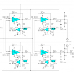
Inspired by this app note, I made my own configuration with paralleling those chips. I will point out below some key features of this en-changed design.
1: All chips are driven differential. No input arm refer to ground, this reduce error's and DC offset's radically.
2: The DC servo's are also a virtual ground, and each input arm sees the same impedance in reference to a (virtual) ground. This keeps the common mode noise reduction of each chip relatively high, assumed 0.1% resistors are used, but this is an absolute need if you parallel chip-amps anyway
About point 2, one could argue that the servo noise is only attenuated by 20 (the same as the voltage gain ratio). But in practice this didn't seems to be a problem. The noise from the servo op-amp is still lower then there would be normally in the ground lines if the positive arm is tied to ground as usual.
The above described design avoid ground noise, provide excellent CMNR for each chip, and reduce errors at the input due the equalized input impedances.
Last but not least, since all chips are driven by truth balanced differential lines, one can design the PCB in a way that this differential pair is layed out as a truth close pair, which reduce crosstalk, by canceling each others magnetic fields.
An more powerful slightly different version of above described circuit performs flawless for a year with insane use and abuse on many loud pro audio exhibitions, and the design never failed so far, is rock solid and sound excellent. In my subjective opinion, paralleling chip amps this way sound excellent and better then a single chip.
However for mid-and high frequencies I still prefer a semi discrete design with a LM4702 or LME49811 VAS chip.
With kind regards,
Bas
Attachments
1000uf at the regulators is not sufficient for chip amps
1000uf at the rectifiers is not sufficient capacitance. I would recommend 10000uf or more on each rail.
It is unregulated supply with 100uF capacitors directly at the chip and 1000uF at the rectifiers (2ft umbilical).
I didn't had a chance to measure the supply fluctuation when clipping. It was basically occuring only on Burmester CDIII, track 10 and Patricia Barber's Companion, track 4.
1000uf at the rectifiers is not sufficient capacitance. I would recommend 10000uf or more on each rail.
- Status
- This old topic is closed. If you want to reopen this topic, contact a moderator using the "Report Post" button.
- Home
- Amplifiers
- Chip Amps
- Paralleling LM4780/3886: any impact on sound quality?