Might not be the proper place for it, but i would not like to open a thread for this.
Would someone be so kind to inspect this design, and tell if it will work or not?
I plan to build it without PCB, just simple point-to-point.
Parts list:
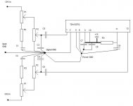
IC TDA1557Q
P1 ->10 K dual gang lin.
P2 -> 50 K dual gang log.
R1=R2 -> 10 K
R3 -> 1K
C1=C2 -> 100nF
C3=C4 -> 150 pF
C5=C6 -> 680nF
C7 -> 3700 uF /25 V elco
C8 -> 100nF
C9 -> 22uF /25 V elco
Supposedly it will be used to power a set of small computer speakers.
Would someone be so kind to inspect this design, and tell if it will work or not?
I plan to build it without PCB, just simple point-to-point.
Parts list:
IC TDA1557Q
P1 ->10 K dual gang lin.
P2 -> 50 K dual gang log.
R1=R2 -> 10 K
R3 -> 1K
C1=C2 -> 100nF
C3=C4 -> 150 pF
C5=C6 -> 680nF
C7 -> 3700 uF /25 V elco
C8 -> 100nF
C9 -> 22uF /25 V elco
Supposedly it will be used to power a set of small computer speakers.
Attachments
uu my bad, i did not provide the description to the schema.
R1+C1+P1 (half of the stereo pot) provides a shelving filter to compensate the rolloff of the small speakers i intend to use.
same applys to R2+C2+P1 (otherhalf of the stereo pot) but only for the other channel on the amp.
C3 and C4 provides some filtering too, setting the high freq. rolloff.
C5+C6 are DC blocking caps,
C7 is reservoir cap,
C8 is to prevent oscillation as datasheet states
R3 and C9 supposedly reduce turn on plop, i have no clue if it will work or not as intended, actualy its just something many kits based on this or similar IC uses, and i only applyd it.
And P2 stereo pot is the volume controll.
The shelving filter is a BSC network, based on
Baffle Step Compensation
this article.
Have not built it, for me it seems a correct schematic, but..... I know my self, so i wait for comments
- Status
- This old topic is closed. If you want to reopen this topic, contact a moderator using the "Report Post" button.
- Home
- Amplifiers
- Chip Amps
- Tda1557q