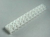
Ok, I was in Radio Shack today and I saw exactly what you were talking about. They were called ground screw terminal or something. It was just a block of metal with 6 holes and screw terminals. So if this is something for the trans. primaries, let me map this out so I can think of this.
AC In--> Switch-->Power Block-->Fuses-->Toroids-->PS
AC In--> Switch-->Power Block-->Fuses-->Toroids-->PS
I was actually just talking about something like in the attached picture. Make sure that vibration and lifting/carrying can't harm the installation wiring inside the amp enclosure. you know that from car audio, but in 110V/220V devices, touching the leads is more dangerous than in a car, y'know...
But take care to bolt the incoming PE (earth) wire directly to the metal chassis, i.e. as shown in this example (scrool down to the trafo picture). Then, connect every single metal part (that could be touched from the outside) to this PE bolt for safety reasons (just like shown in the example). One connection must then exist between each of your PSU grounds and PE (and only one, which also means that any input terminals must be isolated from chassis metal).
Your connection sequence is right (all this is also explained in detail in the example projects I linked to in my previous posts).")
But take care to bolt the incoming PE (earth) wire directly to the metal chassis, i.e. as shown in this example (scrool down to the trafo picture). Then, connect every single metal part (that could be touched from the outside) to this PE bolt for safety reasons (just like shown in the example). One connection must then exist between each of your PSU grounds and PE (and only one, which also means that any input terminals must be isolated from chassis metal).
Your connection sequence is right (all this is also explained in detail in the example projects I linked to in my previous posts).
Attachments
Sebastian,
I just want to say thank you for all your help with this. You have been a great source of information and help. You have made this project seem a lot more completable to me, thanks.
I just want to reword what you said to make sure I am correct. I create one point on the chassis and connect the earth from the AC in to this point, and then any exterior pannel will also be connected to this.
I also need to take care that my inputs are not connected or grounded to the chassis. Should I also try to keep the actual amp boards off of the aluminum of the chassis? I am mounting the chip and board to .25" copper for a heat sink, should this be seperated from the aluminum?
Thanks agian.
Hi Alex,
you're very welcome.
Basically you're exactly right about 'earthing' the panels. But in practice it would be overkill for every single additional panel that already has an electrical connection to an earthed one. It depends on the connection between the panels - and a safety agency would measure and test.
Good practice (and my recommendation) would be to do a PE bolt on a central place with a short PE wire directly from the inlet, and an additional PE wire from the heatsink to that PE bolt. Then, measure resistance between each panel and the PE bolt. If it's more than a couple milliohms (which I doubt), give it an own PE wire to the bolt. Just account for ageing, alluminium corrodes in free air...
Wether your interconnects should be grounded, earthed (note the difference) or left floating depends on your interconnects.
The usual way is the one described in chipamp.com's manual. For standard ('unbalanced') hifi connections like cinch, mount the connectors insulated from the panels. Cinch ground (signal ground) from the cinch socket then goes to the amp board with the (hot) signal wire.
The mentioned manual describes it on page 12. Don't forget the connection from CHG to the PE bolt from each PSU PCB. Page 13 also mentions the safety earthing story.
The amp boards must of course be inulated from any potential (voltage). The boards themselves isolate the mounting holes from the copper. The chip must be mounted on the heatsink with an insulation layer between chip and sink.
Your options for the boards are plastic or metal standoffs or bolts. Both are good.
As for the heatsinking, there are silicone pads, mica washers and ceramic plates availabl. Silicone is the easiest, mica is classic, ceramic looks best.
If you - as per Brian's and Peter's recommendation - use the LM3886TF, you don't have to care for that part, as the TF type is plastic insulated in itself. Just use some silicone grease as heat transfer agent, like on CPU coolers.
The copper heatsink would then not have to be separated from the aluminium. The more metal you have earthed, the better. Just measure the resistances between metal parts after mounting. For conductivity it should be a few milliohms maximum, for insulated parts it should be many many megaohms minimum.
Sebastian.
So far so good. I am gathering parts. The amp itself should be here in 2 days. I am wondering about hook up wires inside. What is everybody using?
Would this suffice? http://www.gepco.com/products/proav_cable/analog_audio/singdual_xband_M.htm
Also, any good brands of Pots. to recommend for a Dual Mono set up?
Would this suffice? http://www.gepco.com/products/proav_cable/analog_audio/singdual_xband_M.htm
Also, any good brands of Pots. to recommend for a Dual Mono set up?
As noone else seems to answer...
The cable you link to looks expensive
And it's for balanced interconnects, something you don't seem to use in this project. But "mono" microphone cable of the same quality should give optimal results.
People use all kinds of cable for internal wiring, a search should come up with a lot of discussion about the topic.
For power wiring, refer to recommended values per given current requirement. PSU wiring should be thick and flexible.
Same for potentiometers, a lot of discussion has been done about this. ALPS (blue series) and Panasonic (plastic tape) are recommended frequently. Just look for something 'encapsuled' with a solid mechanical feel.
Cheers.
sek said:A good toroid has some properties as:... ...and no thermal protection inside (as this works destructive and can't be reset).
Care to elaborate this? I understand the "can't be reset" part but not the "works destructive" part.
A temperature protection device in a transformer is usually a 'thermo-fuse', an element that opens on overtemparature. It then stays open (in order to prevent a fire or other hazard) and the transformer has to be exchanged.
It's bad because of two things: You wreck a transformer by overheating it (which is the least problem, as such high winding temperatures should never happen) - and the variable impedance of the thermal fuse might (possibly maybe) affect the sound.
I've never heard it, though, as I've never overheated a transformer myself.
sek said:Hi again,
If cost permits, You should probably do it.
Let's jump into terminology right here: Power amplifiers of the kind we discuss (e.g. chipamps) need a positive and a negative supply voltage, as they have to resemble both the positive and negative component of the eletrical music signal. You can't get around supplying two voltages of equal magnitude and opposite sign (e.g. +/- 20V).
Those two voltages can be derived out of one single secondary winding, but it has to have a so called center tap, a reference point exactly in the middle of the winding - a third wire. Technically, this would make it a center-tapped 40V secondary winding (denoted as 40Vct or +/- 20Vct).
But as windings on transformers are nonideal, the ct is never exactly in the middle - neither physically, nor electrically. For that reason, a dual secondary transformer is preferable. It can resemble a center-tabbed transformer by connecting the windings together in series (which is why it is always at least as good as a ct one).
The improved performance shows when the two secodary windings get rectified and smoothed independently. The absolute voltage levels might vary under load (as with any real transformer), but the secondaries never 'fight' each other, shifting the amplifiers ground level actually up and down with varying loads. The ground reference point is derived by joining the split supply halves in series at their outputs (instead of at their inputs, so to speak).
This very advantage is not so important with only one single amplifier connected (one could compensate for the drawbacks elsewhere). But two amplifier modules inside the same enclosure actually require a stable ground, as one channel should never be influenced by the signal and load situation of the other.
So the alternatives are: Either two regular ct (or dual secondary, doesn't really matter) transformers for true monoblocks - or one big, quality, dual secondary transformer for a common transformer supply.
Regarding parralleling channels: this doubles the current capability of the resulting amp channel, and thus increases it's power capability into lower load impedances (Ohm's law applies
Hope this helps,
Sebastian.
Let me ask something i really dont understand very well how i need to order the transformers :S
i need the transformers to run an 5 channels AMP. 5 x lm3886.
i was thinking to use 30v on each rail, i read in datasheet that maximum are 35v, so i think that will be ok. i want to run it as high as possible because my Speakers (FR125s) are just 84db/1w. are 30v ok? can i use 32v too?
i want to use 2 transformers, each one need to have just 2 wires right? 2x 0v-30v 200-250VA will be ok?
Thanks in advance.
shouldn't you add the 1,4v for the bridge rectifier before dividing by 1,41?
i own 30+30 VAC (with no load) transformer, 250VA. i guess (i'll measure it today) it will give something like 27+27 VAC loaded. after rectifying:
30*1.41-1.4=41
28*1.41-1.4=38
it should vary within the +-41VDC to +-38VDC range.
pretty tight for a LM3886, right?
anybody tryied this chip so close to the 42V limit? any suggestions besides avoiding it?
thanks.
Hi,
The absolute maximum supply voltage |V(+)| + |V(-)| is stated as 84V. This gives 42V absolute maximum per supply line. Bute the diagrams only specify sensible and safe function up to 70V (i.e. datasheet p. 8).
On p. 9 THD+N is specified for both +/-28V and +/-35V, so anything in between gives results as rated. Anything beyond gets worse. The Power Dissipation vs. Output Power graphs on p. 11 indicate a maximum power loss of 70W when driving 4Ohm from +/-35V. Sinking this heat off is difficult to say the least! For an 8Ohm load and +/-40V the graph indicates a loss of 50W, still a lot.
And it suggests the conclusion that driving 4Ohm from +/-40V would strike the amp with 90W of losses, nothing a chipamp could handle! As you can't guarantee any load impedance to be only well above 8Ohm, this scenario becomes a no-no. Sound-wise, the internal protection circuitry would long have kicked in and ruined the sound. This is also the answer to the actual question: it would work, but that it would sound good at higher volumes is unlikely.
There's no need to have two transformers, one beefier one would be smaller and less expensive. But it seems to be an interesting idea.
Although, 2x 0v-30v don't conform to 2 wires, so I probably don't get what you mean.
What you need ist 2x 0v-30v to each amp, how you supply it is up to you.
From one transformer 2x 0v-30v means exactly three secondary wires.
From two transformers with one secondary each it means two secondary wires per transformer, so four secondary wires total. This is probably what you meant.
As Pinkmouse and Facundonu correctly pointed out, 30V secondary doesn't mean 30V DC supply to the amp.
I recommend +/-35Vmax DC for 4Ohm speakers, +/-40Vmax DC for above 8Ohm. This would lead to 2x 0V-24.75V and 2x 0V-28.3V secondaries, respectively (not accounting for rectifier losses).
Rectifier losses vary with rectifier type. The value 1.4V fits a silicium diode bridge rectifier when cold and loaded with higher currents. In this regard I would recommend to only design for safety - and thus not increase the AC voltage to compensate for the rectifier loss.
Two reasons: first, a Schottky rectifier has less than half this loss, so you never know what everyone wants to use. Second, 1V more output voltage only means 10Wmax more output power in the region of a +/-40V supply. Sound-wise, this gain is negligible, but from a safety standpoint some volts too many are some volts too many.
Cheers,
Sebastian.
i was thinking to use 30v on each rail, i read in datasheet that maximum are 35v, so i think that will be ok. i want to run it as high as possible because my Speakers (FR125s) are just 84db/1w. are 30v ok? can i use 32v too?
The absolute maximum supply voltage |V(+)| + |V(-)| is stated as 84V. This gives 42V absolute maximum per supply line. Bute the diagrams only specify sensible and safe function up to 70V (i.e. datasheet p. 8).
On p. 9 THD+N is specified for both +/-28V and +/-35V, so anything in between gives results as rated. Anything beyond gets worse. The Power Dissipation vs. Output Power graphs on p. 11 indicate a maximum power loss of 70W when driving 4Ohm from +/-35V. Sinking this heat off is difficult to say the least! For an 8Ohm load and +/-40V the graph indicates a loss of 50W, still a lot.
And it suggests the conclusion that driving 4Ohm from +/-40V would strike the amp with 90W of losses, nothing a chipamp could handle! As you can't guarantee any load impedance to be only well above 8Ohm, this scenario becomes a no-no. Sound-wise, the internal protection circuitry would long have kicked in and ruined the sound. This is also the answer to the actual question: it would work, but that it would sound good at higher volumes is unlikely.
i want to use 2 transformers, each one need to have just 2 wires right? 2x 0v-30v 200-250VA will be ok?
There's no need to have two transformers, one beefier one would be smaller and less expensive. But it seems to be an interesting idea.
Although, 2x 0v-30v don't conform to 2 wires, so I probably don't get what you mean.
What you need ist 2x 0v-30v to each amp, how you supply it is up to you.
From one transformer 2x 0v-30v means exactly three secondary wires.
From two transformers with one secondary each it means two secondary wires per transformer, so four secondary wires total. This is probably what you meant.
As Pinkmouse and Facundonu correctly pointed out, 30V secondary doesn't mean 30V DC supply to the amp.
I recommend +/-35Vmax DC for 4Ohm speakers, +/-40Vmax DC for above 8Ohm. This would lead to 2x 0V-24.75V and 2x 0V-28.3V secondaries, respectively (not accounting for rectifier losses).
shouldn't you add the 1,4v for the bridge rectifier before dividing by 1,41?
Rectifier losses vary with rectifier type. The value 1.4V fits a silicium diode bridge rectifier when cold and loaded with higher currents. In this regard I would recommend to only design for safety - and thus not increase the AC voltage to compensate for the rectifier loss.
Two reasons: first, a Schottky rectifier has less than half this loss, so you never know what everyone wants to use. Second, 1V more output voltage only means 10Wmax more output power in the region of a +/-40V supply. Sound-wise, this gain is negligible, but from a safety standpoint some volts too many are some volts too many.
Cheers,
Sebastian.
Thanks too much, i read in the forum that using 2 transformers 0-28 for example, will give better sound that just use one 28-0-28. Thats why i ask abt use 2 instead just one, but one will be cheaper of course, so i think that will use just one.
400VA will be ok for an 5 channels amp? i dont want an bigger trafo, and i cant purchase toroidals, because in my country are too expensive.
So i will goto the store and just ask for 28-0-28 400VA transformer. thats ok right?
400VA will be ok for an 5 channels amp? i dont want an bigger trafo, and i cant purchase toroidals, because in my country are too expensive.
So i will goto the store and just ask for 28-0-28 400VA transformer. thats ok right?
This actually only depends on the power you require. You wrote that you use FR125s with just 84db/1w, that's not a lot.
At 10W, they could deliver approx. 94dB SPL (@1m), for 100dB you'd need at least 40W. The amps would then still have a headroom (dynamic reserve) of 3dB, accounting for power compression and safety margin.
You probably want to max out the dynamic range of the chips, but with almost +/-40V DC this is a total power consumption of 120Wmax per channel. That's 600Wmax per 5 channels.
So for regular casual and occasional party or home cinema listening, a 400W transformer would probably be enough for good sound all the way. It's definitely enough regarding safety, provided you fuse accordingly.
To squeeze the very last out of the chips, a 1000W transformer and active heat sinking would be required, though. But in case it's a 5.1 channel home theater system, this will not be required, because there won't be many moments when all channels get driven hard simultaneously.
In any way, with +/-40V supply lines, the usual small heatsinks are definitely not sufficient any more, especially if you mount five of them into one enclosure. You'll have to cool the thing like a big one (because it actually will be).
Hope this helps,
Sebastian.
PS: Take care! You need heat sinking and capacitor buffering for five amplifiers putting out anything between 2W and 120W each, thats between 10W steady and 600W short term power total.
More LM3886 Suggestions
Hi guys. I hope you don't mind me coming in on this thread but it seems better than to start another new one...
I have built LM3886 amp and am impressed by what I have heard so far. But from other peoples comments I know it's capable of more.
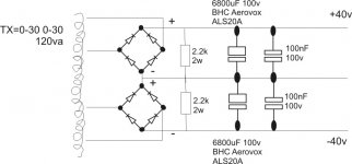
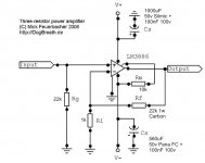
I have attached diagrams of what I have. Could anyone be so kind as to give some suggestions for improvement.
I realise the tx isn't up to scratch and that the local decoupling caps need to be improved but i'm unsure about snubber values etc....
Cheers, Lee.
Hi guys. I hope you don't mind me coming in on this thread but it seems better than to start another new one...
I have built LM3886 amp and am impressed by what I have heard so far. But from other peoples comments I know it's capable of more.
I have attached diagrams of what I have. Could anyone be so kind as to give some suggestions for improvement.
I realise the tx isn't up to scratch and that the local decoupling caps need to be improved but i'm unsure about snubber values etc....
Cheers, Lee.
Attachments
Hi,
I still prefer TNT's approach and what Carlos used to make out of it - as mentioned above - even though it's been a while ago already.
Just make sure you read both topics to their last pages.
And 2x30V is way too high for the transformer, especially at 120W for two channels!
On how to calculate it and what values I recommend, please re-read the whole thread. In my postings above I detailed a lot, I cannot repeat all of it.

Sebastian
I still prefer TNT's approach and what Carlos used to make out of it - as mentioned above - even though it's been a while ago already.
Just make sure you read both topics to their last pages.
And 2x30V is way too high for the transformer, especially at 120W for two channels!
On how to calculate it and what values I recommend, please re-read the whole thread. In my postings above I detailed a lot, I cannot repeat all of it.
Sebastian
- Status
- This old topic is closed. If you want to reopen this topic, contact a moderator using the "Report Post" button.
- Home
- Amplifiers
- Chip Amps
- LM3886 Questions and Suggestions