I've built LM4780 + tube buffer using Joe's design.
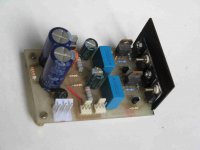
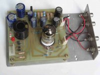
I used p2p construction for chip, so it is very chaotic. 6n1p-vi tube is powered with 130V, 47K cathode resistor. Heaters do run from about 6V unregulated DC supply, grounded to signal ground via 0.1uF capacitor. Pin 9 is grounded too, but in my tests it wasnt audible if it is grounded or is not. As this was my first project with tubes involved, I am experiencing some problems.
1) some noise, audible only when I put my ear to speakers. At beginning it was loud, because I had directly grounded heater. Maybe some grounding issues, as my p2p construction aint too good. Maybe I have missed something. Tube PSU use CRC filter, which is 47uF, 160 ohm, 560uf, bypassed with 0.22uf. Chipamp's PSU consists of E type trafo, 2X21VAC, one bridge rectifier, 4 x 470uf caps + 1 x 1000uF cap, + 3 x 680uF, and 680uF + 0,1uF per rail directly on chip's legs.
Is it worth to change bridge rectifier to ultrafast diodes, or it wont make any changes in sound?
2)I dont use potentiometer, so I am using resistor to prevent input from floating. It only works if I use ~20k or less, is that ok?
And I have heard that mostly people use delay for amp, so tube can warm up, otherwise there can be heard some noises and etc. For 6n1p-vi there's no sound for ~10 seconds and then it appears, without any noises.
And one more thing: it is picking up noise from my usb-modem. I havent isolated LM4780 from chip. If I take a piece of foil, and shield the chip, beeping gets more silent.
Last edited:
Ultrafast diodes will yield no improvements. Your filtering seems a bit on the low side, and i wouldn't use paralleled capacitors, just a pair of beefy ones bypassed with 100nF. That is unless your layout demands it, or if you just had those lying around it's okay.
You can use as low a resistor as 10k. Even lower if your sources are designed to drive headphones (like computer, mp3 player, ipod).
If you're picking up noise, you probably have created a ground loop. Make a proper PCB and it should go away.
You can use as low a resistor as 10k. Even lower if your sources are designed to drive headphones (like computer, mp3 player, ipod).
If you're picking up noise, you probably have created a ground loop. Make a proper PCB and it should go away.
I've built LM4780 + tube buffer using Joe's design...
First tube project, excellent. That was always my intension that this should appeal to those who were comfortable with SS could now also find a project that made a good intro to tube diy.
Now for a couple of things, you say the filaments are unregulated. That could certainly lead to 100-120 Hertz of hum, but also unregulated you get the saw tooth ripple with a lot of harmonics and that makes hum sound dirty and this can radiate into the electrodes of the 6N1P. So I'd check that out. The 6N1P needs about twice the filament current, going from memory, to 6DJ8/6922 tube, so accomodate that.
Yes, a reasonable delay is important, mostly for the rude noises it makes and also, unlikely, damage to speakers?
Grounding is very important and is easy to get wrong. It needs to be analysed and fixed if it is a cause of the problem. Take a look at this page and see if there are things that may be helpful:
Power Supply & Wiring
20K on the input should be fine.
I think you will need a fair bit more than 47uF/160R/560uF - if I understand that right - mainly boost the 47uF and I suggest a lot more than that - try and see if that helps. In fact 560uF/160R/47uF may well work better. The 160R could also be higher value.
I'll leave it there as that should give some things to work with. Re faster diodes etc, get it running properly first and then try that sort of thing later by all means.
Cheers, Joe R.
Hello Joe.
Thanks for your input.
I guess these are not power supply problems, the noise is audible even when I disconnect mains plug for trafos, so it runs on energy stored in capacitors. You are right about filament current, it is 600mA. It is very sensitive, if I close up my hand to input wires/caps it starts to hum. I guess I will try shielding.
AR4,
Would you like to compare your amp with another scheme where you use the same tube input and use a CFP source follower using a mix of MOSFET and bipolar ? This will run off an 18 V supply and has ( yech!.....) capacitor coupling for the phones. In spite of the cap it does sound good.
I can spare you one pcb as soon as they are ready.
Let me know if you would like one pcb to try it out .
Cheers.
EDIT: OK I'm on a wrong thread. I was searching for hybrid headphones amps. This one is for power amps for speakers and I didn't notice that.
Neverthless the offer still stands !
Last edited:
Hope this isn't OffTopic but I have a simple question. Before my PC crashed I had saved a link to a site showing a ChipAmp in a STC-design = SuperTriode Connection (*), where a triode is hooked up as a feedback element for the solid state amplifier. The info (and schematic) is lost, but has anyone seen a design resembling what I have described?
(*) http://www2u.biglobe.ne.jp/~hu_amp/amput3e.htm
(*) http://www2u.biglobe.ne.jp/~hu_amp/amput3e.htm
Above schematic from : http://www.diyaudio.com/forums/tubes-valves/20686-se-sound-p-p-amplifier.html
R.C.
R.C.
Building a valve-buffered Gainclone chip amp.Hello All,
I'm scrolling through the thread and trying to find a copy of Joe's schematic. I obviously could go through all 90 some pages, but maybe someone can help with a link to the schematic and a powersupply suggestion.
Thanks,
Dave
Sorry for being slightly OT. But here are some pictures wrt my post.
Hi ashok!
Schematic (cirsuit) please!

thanks!

Wow, I almost forgot that project ! So many things have happened since.
I can't really remember what I did but will try to find the boards. They should be around here. Give me a few days. I have time only till the 3rd as I am going out of town for 2 weeks. Will try in any case.
Cheers.
Happy New Year to all .")
I can't really remember what I did but will try to find the boards. They should be around here. Give me a few days. I have time only till the 3rd as I am going out of town for 2 weeks. Will try in any case.
Cheers.
Happy New Year to all .
- Status
- This old topic is closed. If you want to reopen this topic, contact a moderator using the "Report Post" button.
- Home
- Amplifiers
- Chip Amps
- Tube with Power IC Output Stage - JLTi