Hope this might help?
Hi Guys
I put this together for anyone needing to do assembly of fault-finding of the HIGC:
Some helpful (I hope) explanations:
1. The tube shown is a BOTTOM VIEW, as if looking at the pins.
2. F & F are the filament pins, 4 & 5. This should be 6.3V DC,
polarity not important.
3. Green Wire Connect "S" Signal Ground to "G" Main Ground, this
'G" should also, ideally, be connected to the chassis. In fact the
only point connected to chassis.
4. Wire labelled "Heavy Duty" should preferably be good quality
heavier stranded type, oxygen free would be good too. Something
like a reasonably good Speaker cable should do the job. Failure to
use something suitable here could result in instability.
5. Red block "Other Channel The same" - only one channel is
shown for the buffer. The parts shown in the block indicates
which of the remaining pins do what.
6. The +/- 35V power supplies are not shown. These should be
separate for each channel as discussed earlier. So TWO plus 35V
supplies are required AND TWO negative 35V likewise. Four in
total with each its own filtering (or regulated if you want to
try that - but adds significant complexity).
7. These +/- 35V can be higher voltages - but keep them Low
Tension. This was always a consideration - a tube buffer with
non-lethal voltages so that even non-tube DIY'ourselfers could
cut their teeth on this. So keep well under 90V as many older
tube versions are rated no more than this (because it is a flat
grid tube), and I would recommend the range 35V-60V.
8. Pin 9 is unused. I have heard from some that it might be a
good idea to ground it. If so, ground it to "S". This may be
tube selection dependant, I am not sure. So far it has never
bothered me.
9. The Volume Pot, shown as 25K, is Log, but other values may
be used, from 10K min, but I prefer 50K myself. Low value pot can
cause bass roll-off with some sources.
10. DON'T forget the 1M resistor mounted right on the LM3875.
RE: Tube Buffer Voltages.
1. Use a DC voltmeter then pin 2 and pin 7 should be 0V relative
to either "S" or "G".
2. Use a DC voltmeter then pin 3 and pin 8 should have about +
1V relative to "G". This indicates that the tube is 'on' and
conducting current.
3. The current can be measured by putting your voltmeter across
the 10K resistor. Let's say it measures 36V, then the calcution
is simple:
36/10000 = 0.0036A
The 36V is devided by the value of the resistor (10K = 10000
Ohm) = 0.0036A or 3.6mA.
4. Next set your voltmeter to AC - and measure all plus and minus
35V rails (four measurements - polarity not important with AC).
This should read as low as possible and hopefully no more than
2-5 mV AC. If too high could give rise to hum.
These basic tests should indicate correct operation of Tube
Buffer.
Hope this might be of help to Tor and others.
Regards
Joe R.
Hi Guys
I put this together for anyone needing to do assembly of fault-finding of the HIGC:
An externally hosted image should be here but it was not working when we last tested it.
Some helpful (I hope) explanations:
1. The tube shown is a BOTTOM VIEW, as if looking at the pins.
2. F & F are the filament pins, 4 & 5. This should be 6.3V DC,
polarity not important.
3. Green Wire Connect "S" Signal Ground to "G" Main Ground, this
'G" should also, ideally, be connected to the chassis. In fact the
only point connected to chassis.
4. Wire labelled "Heavy Duty" should preferably be good quality
heavier stranded type, oxygen free would be good too. Something
like a reasonably good Speaker cable should do the job. Failure to
use something suitable here could result in instability.
5. Red block "Other Channel The same" - only one channel is
shown for the buffer. The parts shown in the block indicates
which of the remaining pins do what.
6. The +/- 35V power supplies are not shown. These should be
separate for each channel as discussed earlier. So TWO plus 35V
supplies are required AND TWO negative 35V likewise. Four in
total with each its own filtering (or regulated if you want to
try that - but adds significant complexity).
7. These +/- 35V can be higher voltages - but keep them Low
Tension. This was always a consideration - a tube buffer with
non-lethal voltages so that even non-tube DIY'ourselfers could
cut their teeth on this. So keep well under 90V as many older
tube versions are rated no more than this (because it is a flat
grid tube), and I would recommend the range 35V-60V.
8. Pin 9 is unused. I have heard from some that it might be a
good idea to ground it. If so, ground it to "S". This may be
tube selection dependant, I am not sure. So far it has never
bothered me.
9. The Volume Pot, shown as 25K, is Log, but other values may
be used, from 10K min, but I prefer 50K myself. Low value pot can
cause bass roll-off with some sources.
10. DON'T forget the 1M resistor mounted right on the LM3875.
RE: Tube Buffer Voltages.
1. Use a DC voltmeter then pin 2 and pin 7 should be 0V relative
to either "S" or "G".
2. Use a DC voltmeter then pin 3 and pin 8 should have about +
1V relative to "G". This indicates that the tube is 'on' and
conducting current.
3. The current can be measured by putting your voltmeter across
the 10K resistor. Let's say it measures 36V, then the calcution
is simple:
36/10000 = 0.0036A
The 36V is devided by the value of the resistor (10K = 10000
Ohm) = 0.0036A or 3.6mA.
4. Next set your voltmeter to AC - and measure all plus and minus
35V rails (four measurements - polarity not important with AC).
This should read as low as possible and hopefully no more than
2-5 mV AC. If too high could give rise to hum.
These basic tests should indicate correct operation of Tube
Buffer.
Hope this might be of help to Tor and others.
Regards
Joe R.
Hi,
It does provide for better channel separation... provided other wires carrying signal are sufficiently kept apart.
Cheers,")
8. Pin 9 is unused. I have heard from some that it might be a good idea to ground it. If so, ground it to "S". This may be
tube selection dependant, I am not sure. So far it has never
bothered me.
It does provide for better channel separation... provided other wires carrying signal are sufficiently kept apart.
Cheers,
Re: Hope this might help?
Thanx for that Joe ... an instruction manual of sorts.
Pin 9 on some tubes is the shield between triode sections.
A trick that often helps reduce filament induced hum, is to wire the trafo as shown.
dave
Thanx for that Joe ... an instruction manual of sorts.
Joe Rasmussen said:8. Pin 9 is unused. I have heard from some that it might be a
good idea to ground it. If so, ground it to "S". This may be
tube selection dependant, I am not sure. So far it has never
bothered me.
Pin 9 on some tubes is the shield between triode sections.
A trick that often helps reduce filament induced hum, is to wire the trafo as shown.
dave
Attachments
Hi,
It is for all 6DJ8s and family such as the 6N1P and other modern folded anode tubes.
That trick works best for AC fed heaters, especially for DHTs where a balancing pot, AKA rheostat is often desireable for humbucking.
It can be applied to the powerxformer or at the heater pins, whatever is more convenient.
It mimmicks a CT xformer.
With DC on the heaters, as should be the case here, it's not effective but it won't hurt either.
Sorry,
Pin 9 on some tubes is the shield between triode sections.
It is for all 6DJ8s and family such as the 6N1P and other modern folded anode tubes.
A trick that often helps reduce filament induced hum, is to wire the trafo as shown.
That trick works best for AC fed heaters, especially for DHTs where a balancing pot, AKA rheostat is often desireable for humbucking.
It can be applied to the powerxformer or at the heater pins, whatever is more convenient.
It mimmicks a CT xformer.
With DC on the heaters, as should be the case here, it's not effective but it won't hurt either.
Sorry,
Hi!
I did some bias measurements and got som veird readings. I also found that my tube buffer were not made for measurenents, components to close to tube socket...........................
The weather is realy nice, and warm!! Making my brain not function 100 %, so I think I`ll make a new tube buffer with a different layout and seperat supply for each channel.
Have to get a new tube first.....
Thanks Joe for brilliant advice!
P.S I`m learning alot from this!!! Maybe it`s a good think that everything is not working properly right away.
I know I`ll get it right at the end.
I have tasted the pudding, and the pudding is good!
Have been working a night shift, got to get some sleep.
Tor Martin
Hi Guys
Re Pin 9 being grounded or not, maybe the reason it has never been of concern to me: I don't usually share Left & Right channels in a single tube (or envelope), so channel cross-talk was never a concern.
In the JLTi, I have used separate Sovtek 'Reflector' 6922, Left and Right. Both Pin 9s are left alone.
So in this case, the DIY HIGC Project, with its shared channels, I would think it's a good idea to ground Pin 9. It can be done either at "G" or "S" - whichever is more convenient.
Mind you, not much point IF you use a volume pot with pour channel separation.
Re AC Heaters:
I don't usually use AC on heaters where there is a lot of gain at that point or subsequently further up the chain. Whenever I do use AC, then Dave's solution is the same that I've always applied.
But of the two techniques Dave has shown, I prefer paired 1% resistors (Dave's 2nd diagram) as they are likely more accurate, than tx centre-taps. The idea here is to cancel or 'nul' the AC - I mention this for those not familiar with AC heaters. Besides, sometimes you may a 6.3V AC Transformer without centre-tap. In that case, no worries.
BTW, I just heard on the radio that Americans are starting to pick up a lot of Australianisms, one example the quoted was no worries which is short for no worries mate.
Lesson over....
Joe R.
BTW, I just heard on the radio that Americans are starting to pick up a lot of Australianisms, one example the quoted was no worries which is short for no worries mate.
Which is short for no wucking furries mate!
Joe Rasmussen said:BTW, I just heard on the radio that Americans are starting to pick up a lot of Australianisms, one example the quoted was no worries which is short for no worries mate.
They may be partly picking that up from is Canadians (which we picked up from Aussies -- my high school had both Australian exchange students & teachers (i had a real sweet Grade 10 English teacher
) -- that phrase has been in use around here for many years.dave
Finally no hummm
Again I want to thank everyone for their help, this little guy has been a real learning experience.
As the subject states I finally have a hum free amp. What fixed it is a little odd though. I decided to open up my other gainclone to compare groundings and hookup and notice that I didn't have the caps on the chips but in a seperate PS providing +/- for both chips. So I did the same for the hybrid and yureka no more hum. My grounds may have been off, but who knows.
I'm gonna take some time and enjoy it and when I have time to build a suitable chasis I wll post some picks.
Regards...Lee
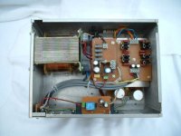
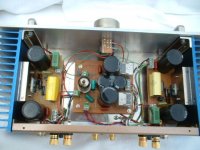
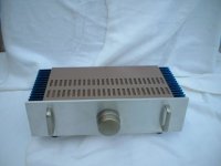
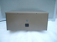

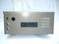
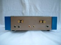
Hi everybody, thanks for all your compliments, I am still trying to improve my work.
Nuuk, as for your query on the connection to psu, I have attached pictures and the circuit diagram. As for tube power supply, I am using a relay as a choke. This idea came from Mr Kristijan Kljucaric of PCB Design site.
Regards
Tony
Nuuk, as for your query on the connection to psu, I have attached pictures and the circuit diagram. As for tube power supply, I am using a relay as a choke. This idea came from Mr Kristijan Kljucaric of PCB Design site.
Regards
Tony
Attachments
- Status
- This old topic is closed. If you want to reopen this topic, contact a moderator using the "Report Post" button.
- Home
- Amplifiers
- Chip Amps
- Tube with Power IC Output Stage - JLTi