ShanaVar said:Ok i read through some of the pages now (~20-30) of this topic and i got some yes/no questions.
1) Is the on Customanalogue the final one? Or is there a "better" somewhere hidden inside this thread?
2) I want to lower the output power... Can i achieve this by the lowering supply voltage of the lm3875 (say to ~+-25V) and keep the rest of the circuit as it is without bad effects on the sound quality?
3) If i can lower the rail voltage as i did describe above, can i use the same psu as for the tube for the lm3875 on the homepage above(customanalogue) and will a 200VA trafo be sufficient then?
greets and thanks,
Patrick
Hi Patrick
I think generally the answer is yes to all your questions. Although I might suspect that the LM3875 will sound better at the higher voltage. I haven't actually any confirmed answer to this case, just general experience with 'opamps' - they always seem to sound a little bit better when nearer their max voltage rating, but not going beyond it.
Re the T-Network, I prefer an alternative that may not be for everybody. May I suggest you build it as shown and take a listen. Then come back here and ask for the alternative T-Network that has lower feedback.
Re requirements for the tube front-end, they do not change.
Joe R.
Joe Rasmussen said:Although I might suspect that the LM3875 will sound better at the higher voltage.
It seems to depend on the speakers the load presents... on higher impedance speakers higher voltage works better (i have one with rails just a bit higher than max and it sings on 16 ohm speakers)... impedances that require more current prefer lower rails... 25VDC is about optimum for 4 ohm loads.
dave
ok so my speakers are 8ohm. The problem is, my tweeter is only capable of 50W and i read that the output is about 57W@8ohm and 100W peak. So i have to reduce the output power a little. Is the high peak a problem for 50W speakers? Because i see in the datasheet that if i reduce the supply voltage to 20-25V i get an output power of 20-30W and could use a 160VA transformator(can i ?). Is this too much reduction or is it ok? (Less power includes more THD according to the datasheet)
Greets and thanks,
Patrick
PS: i saw that THD goes down with more output power. Maybe thats a reason it "sounds" better with higher supply voltage?
Greets and thanks,
Patrick
PS: i saw that THD goes down with more output power. Maybe thats a reason it "sounds" better with higher supply voltage?
ShanaVar said:ok so my speakers are 8ohm. The problem is, my tweeter is only capable of 50W and i read that the output is about 57W@8ohm and 100W peak. So i have to reduce the output power a little.
Hi Patrick
I believe that is false reasoning. With tweeters it is really about the thermal limit - indeed any reasonable tweeter can hand a 10KHz 1KW of power for one milisecond. Don't quote me on this, I am just illustrating that such a short term peak will not really heat up the voice coil enough. I can tell you that most tweeters can only handle a few watts of continuous signal as THIS will heat up the voice coil and the pour coil will not have a break and cool down. But music gives you plenty of time between the peaks. So I am explaining in the simplest terms that you don't really have a problem, go ahead and build it. The extra head room in power is an asset rather than a danger, in most cases.
Yes, Dave, I reckon with 4 Ohm loads that something nearer 25V would be about right. I note that when running the usual 35V rails and 1000uF/50V FC caps, then before clipping into 8 Ohm the rails have dropped to near 30V and going much beyond that you get lots of 100 Hertz break-through by the time it clips - circa 45 Watts into 8R. So there is a good argument for using 2200uF with 8 Ohm loads.
BTW Dave, a bit off topic, have you tried Bill Perkins idea of triode mode?
Joe R.
Patrick, when an amplifier is quoted as being say 50 watts, it means that is what it may be capable of producing at full power, ie with the volume control set to maximum.
I previously used Goodmans 201 drive units rated at (only) 20 watts. I used them with a variety of GCs (including the VBIGC that ran on 38 volt rails), and there was no problem because I never abused them by turning the volume control too high.
I previously used Goodmans 201 drive units rated at (only) 20 watts. I used them with a variety of GCs (including the VBIGC that ran on 38 volt rails), and there was no problem because I never abused them by turning the volume control too high.
"So there is a good argument for using 2200uF with 8 Ohm loads."
Correction: That should have read: "So there is a good argument for using 2200uF with 4 Ohm loads."
Hi Nick, how's things going?
Re JLTi and gainclone matters, I've got this thing here that can be added to the gainclone circuit, yet to be revealed. It kind of keeps the amp from being parked in the zero volt - we're talking crossover distortion here. When a signal that is lowish in level, the time it takes to cross that critical region is actually longer since the acceleration, which is a function of both amplitude and frequency, is slow. But by accelerating it through the crossover region (a modulating effect) at a higher frequency... it actually works. But I just won't let the cat out of the bag yet. The current commercial version (now Mk3) of the JLTi Hybrid Integrated uses it, and it is quite a noticeable improvement. It is the final piece of the puzzle, IMO, for the ultimate gainclone.
Joe R.
ShanaVar said:ok so my speakers are 8ohm. The problem is, my tweeter is only capable of 50W and i read that the output is about 57W@8ohm and 100W peak. So i have to reduce the output power a little.
With tweeters it is better to have more power than less... what kills tweeters is the running out of power.
dave
Joe Rasmussen said:BTW Dave, a bit off topic, have you tried Bill Perkins idea of triode mode?
]
Not yet, but high on the list. We have to find a sub for the zener, the obselete part Bill specced is very dear. I did note your comment with the picture of the Yaqin EL34 amp (we are on parallel tracks here -- i have one on the banch and it has been getting a serious workover -- mail me if you want to chat about the detail)
dave
It is the final piece of the puzzle, IMO, for the ultimate gainclone.
I am despatching several members of MI6 to track you down Joe and get the dastardly secret out of you!

I'm still using GC's so I look forward to this little tweak if and when you go public!
Joe Rasmussen said:Re JLTi and gainclone matters, I've got this thing here that can be added to the gainclone circuit, yet to be revealed. It kind of keeps the amp from being parked in the zero volt - we're talking crossover distortion here. When a signal that is lowish in level, the time it takes to cross that critical region is actually longer since the acceleration, which is a function of both amplitude and frequency, is slow. But by accelerating it through the crossover region (a modulating effect) at a higher frequency... it actually works.
Sounds similar to adding high frequency AC bias to a signal to reduce distortion on an analog tape.
BWRX said:
Sounds similar to adding high frequency AC bias to a signal to reduce distortion on an analog tape.
OK, go for it!
Joe R.
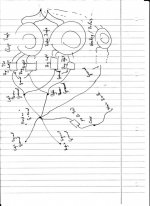
As i have slowly aquired all the parts and the idea for the case comes more clear I thought about grounding the jlti.
I will use 3 Transformers, one for the Chips (2x regulated PSU), one for the Tubes (maybe 1x or 2x regulated) and one for the Heating and the rest of the stuff. I drew a picture of how I would do the grounding. Maybe somebody can take a look and give me a go.
Thanks in advance, Shanavar
I will use 3 Transformers, one for the Chips (2x regulated PSU), one for the Tubes (maybe 1x or 2x regulated) and one for the Heating and the rest of the stuff. I drew a picture of how I would do the grounding. Maybe somebody can take a look and give me a go.
Thanks in advance, Shanavar
Attachments
My neck is a bit sore and my eyes not so good at this time of night so I will just offer how I did it .
milen007 said:can the 6922 be replace by 12ax7 or 12au7 or 12b4?
12au7's your best bet. lower mu and lower Gm, but neither of those probably matter that much here.
milen007 said:newbie question,
i would like to build this, but do not have 6922 at hand
can the 6922 be replace by 12ax7 or 12au7 or 12b4? guess not ? as i have these 3 tube in the closet.
thx in adv
You could, but the positive supply needs to be a lot higher, in which case you might as well make the negative the same and adjust cathode resistor to negative to give 3-4mA.
Mind you, the original reason for choosing 6922/6DJ8 was to encourage those who had previously felt reluctant making tube DIY (high voltages can be scary) and to do their first tube DIY project with voltages no higher than SS. There will never be an easier introduction to tube DIY. I think it has been quite successful in that regard. Many would never have tackled tubes otherwise and also it gives many the confidence to embrace it further.
Joe R.
milen007 said:hi Joe R
thanks for the input. whats your recommended supply for the 12au7 or 12ax7 or maybe 12b4? i did tube preamp before. hence high voltage is acceptable. thx in adv
regards,
Erwin
I would choose 12AU7 and get a minimum 80V and preferably 100V and even more won't hurt - and 5mA and even up to 10mA. You could use one half of the U7 as the follower and the other half as a current source to neg supply, in which case the neg supply should be the same as the positive.
Joe R.
Hi,
I am in the process of acquiring the parts for building this amp. Has anybody used a CLC designed power supply for the tube power? I happen to have a 22H choke in the closet just waiting for a project. The DCR of this choke is about 260, close to the resistor used in the CRC filter. Thoughts, ideas, suggestions?
Jeff
- Status
- This old topic is closed. If you want to reopen this topic, contact a moderator using the "Report Post" button.
- Home
- Amplifiers
- Chip Amps
- Tube with Power IC Output Stage - JLTi