Finally!!
Hi!!
My tube buffered gainclone made after Joe`s schematics has been up and running for å couple of days. And it sounds fantastic!")
This was my first amp build and my first time playing with tubes.
I did some beginners mistakes ( wiring the tube socket as seen from above, not from the bottom...................) But after a couple of hours of rewireing this amp bypassed my 2000$ Electrocompaniet ECI1 (My daughter killed this one, and I`ve been out of an amp for a couple of months.) in sound quality without hardly any playing time!.
So thank you Joe!
And spesial thank to Peter Daniel for sending me isolation pads all the way from Canada to Norway!
But sadly I`m not quite in HiFi heaven yet. I`ve got hum!!!!!!!!
The hum is constatnt (and quite annoying!) and does not change if I have an input source or not.
When I turn the pot I got DC on the outputs, you can see the elements "pushing" out when turning volume down, and going in when turnig up.
Besides that it has no DC on the output when the tube buffer has stabilised.
I also have power transients coming in to the system when I turn the power section on or of, and sometimes I get transients when a light swich is turned.
I have a wooden cabinet which is not shealded, and I have no capasitor over the power swich.
Maybe it would help to add an X rated capasitor over the swich or a three legged x and y rated capasitor over the power input to kill those transients?
I have tried several ways for the grounding to see if I can reduce the hum, but it remains the same. I also tried to wrap the cabinet in aluminium foil connected to earth (no connection too star grounds) to see if this could reduce hum without any result.
At the moment I have one signal star ground and one power star ground pr channel, theese are connected by a wire. The power grounds are also connected.
The chips are not running hot at all, even when pushed hard.
If somebody have any idea of how to get my new amp hum free, I would be realy grateful if you shared them with me.
Thanks to everybody posting here sharing their ideas! This was my first amp build, I doubt it will be the last! (Oh no!! Another adiccted person!!)
Tor Martin
Hi!!
My tube buffered gainclone made after Joe`s schematics has been up and running for å couple of days. And it sounds fantastic!
This was my first amp build and my first time playing with tubes.
I did some beginners mistakes ( wiring the tube socket as seen from above, not from the bottom...................)
But after a couple of hours of rewireing this amp bypassed my 2000$ Electrocompaniet ECI1 (My daughter killed this one, and I`ve been out of an amp for a couple of months.) in sound quality without hardly any playing time!.So thank you Joe!
And spesial thank to Peter Daniel for sending me isolation pads all the way from Canada to Norway!
But sadly I`m not quite in HiFi heaven yet. I`ve got hum!!!!!!!!
The hum is constatnt (and quite annoying!) and does not change if I have an input source or not.
When I turn the pot I got DC on the outputs, you can see the elements "pushing" out when turning volume down, and going in when turnig up.
Besides that it has no DC on the output when the tube buffer has stabilised.
I also have power transients coming in to the system when I turn the power section on or of, and sometimes I get transients when a light swich is turned.
I have a wooden cabinet which is not shealded, and I have no capasitor over the power swich.
Maybe it would help to add an X rated capasitor over the swich or a three legged x and y rated capasitor over the power input to kill those transients?
I have tried several ways for the grounding to see if I can reduce the hum, but it remains the same. I also tried to wrap the cabinet in aluminium foil connected to earth (no connection too star grounds) to see if this could reduce hum without any result.
At the moment I have one signal star ground and one power star ground pr channel, theese are connected by a wire. The power grounds are also connected.
The chips are not running hot at all, even when pushed hard.
If somebody have any idea of how to get my new amp hum free, I would be realy grateful if you shared them with me.
Thanks to everybody posting here sharing their ideas! This was my first amp build, I doubt it will be the last!
(Oh no!! Another adiccted person!!)Tor Martin
Hi Tor,
Happy for you, but the hum...
Assuming that you are indeed new to tubes, one thing you need to be aware off:
When you feed the heaters of a tube with AC you better twist both wires together an keep them close to the groundplane and away from anything else.
This may be one reason for the hum you're experiencing.
Another reason may be capacitive coupling on the powerxfomer when the heater and main PSU share the same xformer inducing hum in the process.
In case you do use separate xformers try to put them at 90 degrees angles, in which case magnetic coupling tends to cancel.
Cheers,
Happy for you, but the hum...
This was my first amp build and my first time playing with tubes.
Assuming that you are indeed new to tubes, one thing you need to be aware off:
When you feed the heaters of a tube with AC you better twist both wires together an keep them close to the groundplane and away from anything else.
This may be one reason for the hum you're experiencing.
Another reason may be capacitive coupling on the powerxfomer when the heater and main PSU share the same xformer inducing hum in the process.
In case you do use separate xformers try to put them at 90 degrees angles, in which case magnetic coupling tends to cancel.
Cheers,
Re: Finally!!
Hi Tor
Good to hear you are so pleased, hopefully even more so when the problems have been sorted out.
We will certainly want to help you get it right, and perhaps collectively we can come up with some suggestions:
To get the ball rolling, can you confirm/answer these below:
1. Are you using separate Bridges and 1000uF x 2 per each LM3875?
2. Are you using separate Bridges and 1000uF x 2 per each for both Right and Left channels on the tube buffer.
3. Is the fault/hum the same on both channels? Is the problem when changing pot likewise on both channels?
IF the answer is yes to all three it may indicate a wiring fault(s) that has been repeated on both channels?
Give us an indication, and we will take from there. The brains trust (that us lot) can take it from there and we''ll get you home.
JR
PS: It doesn't sound (no pun intended) like a shielding problem.
Tor M said:Hi!!
But sadly I`m not quite in HiFi heaven yet. I`ve got hum!!!!!!!!
The hum is constatnt (and quite annoying!) and does not change if I have an input source or not.
When I turn the pot I got DC on the outputs, you can see the elements "pushing" out when turning volume down, and going in when turnig up.
Besides that it has no DC on the output when the tube buffer has stabilised.
I also have power transients coming in to the system when I turn the power section on or of, and sometimes I get transients when a light swich is turned.
I have a wooden cabinet which is not shealded, and I have no capasitor over the power swich.
Maybe it would help to add an X rated capasitor over the swich or a three legged x and y rated capasitor over the power input to kill those transients?
I have tried several ways for the grounding to see if I can reduce the hum, but it remains the same. I also tried to wrap the cabinet in aluminium foil connected to earth (no connection too star grounds) to see if this could reduce hum without any result.
At the moment I have one signal star ground and one power star ground pr channel, theese are connected by a wire. The power grounds are also connected.
The chips are not running hot at all, even when pushed hard.
If somebody have any idea of how to get my new amp hum free, I would be realy grateful if you shared them with me.
Thanks to everybody posting here sharing their ideas! This was my first amp build, I doubt it will be the last!
Tor Martin
Hi Tor
Good to hear you are so pleased, hopefully even more so when the problems have been sorted out.
We will certainly want to help you get it right, and perhaps collectively we can come up with some suggestions:
To get the ball rolling, can you confirm/answer these below:
1. Are you using separate Bridges and 1000uF x 2 per each LM3875?
2. Are you using separate Bridges and 1000uF x 2 per each for both Right and Left channels on the tube buffer.
3. Is the fault/hum the same on both channels? Is the problem when changing pot likewise on both channels?
IF the answer is yes to all three it may indicate a wiring fault(s) that has been repeated on both channels?
Give us an indication, and we will take from there. The brains trust (that us lot) can take it from there and we''ll get you home.
JR
PS: It doesn't sound (no pun intended) like a shielding problem.
fdegrove said:Hi Tor,
Happy for you, but the hum...
Assuming that you are indeed new to tubes, one thing you need to be aware off:
When you feed the heaters of a tube with AC you better twist both wires together an keep them close to the groundplane and away from anything else.
This may be one reason for the hum you're experiencing.
Another reason may be capacitive coupling on the powerxfomer when the heater and main PSU share the same xformer inducing hum in the process.
In case you do use separate xformers try to put them at 90 degrees angles, in which case magnetic coupling tends to cancel.
Cheers,
I wouldn't suggest AC when you have 30dB of gain after that stage. If that is is the problem then the answer is simple... but is it AC? We'll hear from Tor. About txs, same again.
JR
Hi!
Thanks for the answers.
I have four transformers in my gainclone.
For the LM3875 I use 2X 300VA 25V transformers, 2 bridges pr chip, one for + and one for -.
For the filament I use 15VA 9V transformer. The cicuit is the same as shows on Joe`s www, besides that I use LM317, a multiturn pot and a 330 ohm resistor, to adjust the voltage to exactly 6.3 V.
For the tube supply I use 30 VA 25 V transformer. One bridge and 2 X1200uF Panasonic FC used for both "sides" of the tube buffer.
All the diodes are Onsemi Mur 860.
All the transformers are of this type:
http://www.en.rs-components.no/cgi-...o02ie&3234082440=3234082440&catoid=-990928665
The hum is the same in both channels, and the problem when changing pot is also the same in both channels.
Unfortunaly I can`t post any pictures yet. Have to borrow a digital camera first.
Hope I can get the amp hum free. I`ve allready fallen in love with it!
Do you think x-rated capasitor over the power swich, and y rated capasitors from N and L to ground on the IEC socet will help me get rid of the power supply transients?
Thanks for the help!
Tor Martin
prototype
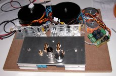
This is my Tubed GC prototype following Joe's schematics.
The amp is assembled using industrial standard components.
PSU is 2x220 VA xformers with 25 V rails for the LM3875, one 15VA
for the heater and one 50VA for both sides of the triode.
I mounted the PSU in a MDF sheet, whereas the amp is built joining
an aluminium plate with two heatsinks for the chips. I used parts
that I had at hand. Also the tube shares the same plate, so it is
a very compact arrangement.
I was exactly in the same situation described by Tor Martin in his post,
i.e. first experience with tubes and hum in both channels either with
input connected or not and independent of the volume pot level.
Yesterday night I split the supply of the left and right channels
of the tube buffers (separate bridges and caps, still sharing the
same transformer). This has helped in reducing the hum,
which is still present but much more acceptable. I have not
tried to change the ground routing yet.
The amp has worked few hours, and I think it needs to break in
properly. I just compared it with my other diy amp, which is a
10W Son of Zen. I found the deep and mid bass performance of the
tubed gainclone very impressive. The bass is deep and very controlled.
The Tubed GC made me discover how powerful can be the bass performance
of my speakers. It was much better than the SOZ bass. In the mid and
high range I found that the SoZ is much more forward and lively.
The Tubed GC provide a much softer sound, may be some people could prefer it
(and my wife likes it very much!!). But sometimes seemed to me a bit dark.
I also find that overall the dynamics of the SOZ is much more superior.
Another point is that as a "summer" amp the Tubed GC is much more fresh
(my SOZ produce an awful quantity of heat).
I would appreciate some suggestion to tweak the project in order to
clarify a bit mids and highs. However, I think that I should listen again
after the break in.
I just want to thank all the contributors to the Forum and Joe for
sharing this project which I enjoyed so much.
Carlo
Attachments
Hi Carlo.
Good to hear that I`m not the only one having problems, but sorry for you.
I think I will rewire the tubebuffer this weekend and try split supply also and se if it can help my amp as well.
I actually have a spear transformer I can use. I ordered one 25 V 30 VA transformer, I payed for one, but RS sent me two!!
Maybe they knew I was gonna need it!!
If I get the time I`ll try to bypass the tube section to night to see if the problems get less without it. Then, maybe I know what to focus on.
Nice amp Carlos. Looking forwart to hear about your impressions when the amp has broken in.
Have a nice weekend!
Tor Martin
Hi Tor,
Not quite sure exactly what is was you did here...
If, as you said, you bypassed the tube buffer stage and ran the splitter xformer straight from the source (as I understand it) then I am at a loss on how putting a 330 R between cathode and grid of the CF is going to have any influence?
Or lets's just say that I don't have the foggiest on how a 300R between cathode and grid is going to solve a hum prob.
Probably my ignorance but I'm curious nonetheless.
Do you mind elaborating on this?
Ta,
I bypassed the tubebuffer in my amp by disconnecting the two trafos and inserting two 330 ohm resistors in the tube socket between K and G. Now the amp is absolutely 100% hum free!
Not quite sure exactly what is was you did here...
If, as you said, you bypassed the tube buffer stage and ran the splitter xformer straight from the source (as I understand it) then I am at a loss on how putting a 330 R between cathode and grid of the CF is going to have any influence?
Or lets's just say that I don't have the foggiest on how a 300R between cathode and grid is going to solve a hum prob.
Probably my ignorance but I'm curious nonetheless.
Do you mind elaborating on this?
Ta,
If, as you said, you bypassed the tube buffer stage and ran the splitter xformer straight from the source (as I understand it) then I am at a loss on how putting a 330 R between cathode and grid of the CF is going to have any influence?
This is what he did to fix his hum:
All this does is prove the tube buffer portion is the issue and not the chip portion, as he stated.
Attachments
leadbelly said:
This is what he did to fix his hum:
All this does is prove the tube buffer portion is the issue and not the chip portion, as he stated.
Agreed!
Check carefully the wiring around the tube buffer. Measure that you have around +35V and -35V.
If the tube is drawing decent current that could explain it as well.
Make sure that you know what the pin connections are on the tube. Just in case they are.
Pin 1. First Anode (or Plate)
Pin 2. First Grid
Pin 3. First Cathode
Pin 4. Filament A
Pin 5. Filament B - both of these are largely interchangeable
Pin 6. Second Anode (or Plate)
Pin 7. Second Grid
Pin 8. Second Cathode
Pin 9. UN-USED
The pins are numbered clock-wise when looking at its bottom, pins facing you.
IF the hum doesn't change with volume control changes, then we could have too much ripple on the +/- 35V power supply. Put you volt-meter (or DMM) to highest sensitivity mV range and measure the ripple on these two rails.
Also the 10K resistor, measure and be sure you have 35V DC across it. This should ensure that you have the required current running through the 'buffer' or tube.
Make sure that what you have is 10K (or near it but no higher). 100K could have been put there by mistake? The colour coding can be deceptive, also it is not unknown to buy 10K resistor from a 10K drawer at the shop and finding they got it wrong and it was 100K. The result here: Reducing the current by a factor of ten could lead to funny misbehaviour? Use a meter to make sure of its value.
Keep at it! With a little patience we'll get it right yet.
Try these things and give us the feedback.
JR
fedde said:How can you measure the ripple on a +35V DC signal with a multimeter in the mV range !? Am I missing something !?
Fedde
Hi Fedde,
Very simple. But putting the volt-meter (or DMM) to AC.
It won't measure the DC component (in effect DC gets 'filtered' out in AC mode) and the meter will show the RMS value of the ripple.
This is useful, especially if you don't have a scope around. Even when using a scope to look at AC ripple, you need to switch the input to AC.
I simulated the power supply, 25V - 3.5mA - 1000uF caps, and it indicated about 5 to 10 mV AC ripple. Now I am not really sure how much this will appear on the output? In my JLTi amp I do regulate this and nothing shows up on an AC volt-meter or scope, no ripple!
If this (ripple) is the source of the hum, then doubling the 1000uF value or use 2200uF will halve the hum, lessen it by -6dB. This should be very noticeable, but IF it doesn't reduce audible hum, then the problem is elsewhere.
JR
Gainclonimpics
As planed I did a listening session comparing 4 different GC based amps. There were: inverted LM3875 dual mono GC, noninverted LM3886 GC (with 2x2200uF/ch. filter caps), noninverted TDA7294 GC and moamps' hybrid GC.
Source was modified Marantz CD4000 and speakers were DIY two-way with Accuton C12 and C95T6 drivers. I used Sowter attenuator based passive preamp to exclude influence of different potentiometers in amps. I listened to the amps for 3 days and here are the results:
The best was moamps' gainclone - very natural sounding, lots of air and great soundstage, except a little bit less control in bass than other GC's, but easily my favourite.
TDA7294 GC was second best - a touch more agressive and a bit smaller soundstage, but better bass control.
LM3875 GC was very bright (to much for my taste) but had excellent dynamic contrast (the best of all).
LM3886 was the worst - small soundstage and agressive, dirty highs.
I would say that HGC is the way to go!
Joe Rasmussen said:
Very simple. But putting the volt-meter (or DMM) to AC.
Whoops! You have to realize it's weekend and I was just awake
Fedde
fedde said:
Whoops! You have to realize it's weekend and I was just awake
Fedde
Hi Fedde,
Rightie-oh! What's it called?
 I am sure it's only pure for medicinal purposes, OK?
 Don't you just love those little smilies?
Seriously though, I am wondering if the problem we've encountered, and I agree it's something to do with the buffer, is indeed power supply hum?
Moamps HGC doesn't seem to suffer at all (seems like the his HGC is getting nods of approval, so we'd want to get them all working right).
Could moamps enlighten us. His power supply configuration is different, I notice as I've just taken a peek at it.
Moamps uses 45V rails (OK by me), could he tell us what ripple RMS he has. Then Tor could do the same and we can compare.
If a series resistor 220R 1/2W and 100uF electros - Panasonic FC would be nice - (on both rails), to give us a Pi filter, then ripple should be under 0.5mV. In hindsight that is what I should have specified? I really thought 1000uF would be enough, and now I wonder if the 5-10mV RMS ripple is the cause of persistent low-level hum.
Using Duncan's PSU Designer II simulation program, adding the Pi filter seems to be the way to go . Moamps configuration may well have got it right when I didn't.
Please keep in mind (forgive me) I didn't actually build this PS, and also that I did SuperReg it in the JLTi - which is where I got my hands-on experience with HGC.
JR
Hi!
Thanks for the help.
This weekend I have been enjoying the unusualy nice weather with my family, barbequing, drinking cold bear and enjoying the sound on my humfree tubebuffer bypassed gainclone.
I hope I get the time to start rearrange my tube buffer tonight.
I think I`ll start with seperate bridge for each channel and add capasitors to the supply and se if that could help.
Tor Martin
Tor M said:Hi!
Thanks for the help.
This weekend I have been enjoying the unusualy nice weather with my family, barbequing, drinking cold bear and enjoying the sound on my humfree tubebuffer bypassed gainclone.
I hope I get the time to start rearrange my tube buffer tonight.
I think I`ll start with seperate bridge for each channel and add capasitors to the supply and se if that could help.
Tor Martin
Hi Tor
I am now of the opion that you have power supply ripple coming through the output of the tube buffer. I had a good look at moamps circuit (he had no hum by the sound of it), his PS schematic shows a tx that he seems to use as a (cancelling?)choke and then looking at the actual main schematic of buffer & GC chip, he uses 6800uF caps. These with the aforementioned 'chokes' and reservoir caps before that, forms an effective Pi filter and I suspect virtually zero ripple (well done moamps, you got something right that I didn't).
Did anyone spot my earlier mistake re Pi filter... ???
My suggested fix, if my hunch is right, is to add an RC filter, something like 220 Ohm and 100uF (min) after the 1000uF. Give that a go.
JR
- Status
- This old topic is closed. If you want to reopen this topic, contact a moderator using the "Report Post" button.
- Home
- Amplifiers
- Chip Amps
- Tube with Power IC Output Stage - JLTi