Hi all,
FINALLY got my LM3875 together (using Peter's boards and parts). I am very happy with the results, although I find it a little bright and perhaps lacking some bass umph. I am unsure which of the following could be the cause of this:
- choice of parts (electronics)
- grounding layout
- smallish supply voltage of +-21V
- maybe something is not hooked up just right
- maybe it's just my speakers (70's Rega, dome tweeters, 7" woofer, ported)
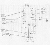
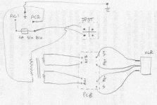
Could you please look over the picture attached below and let me know if you see anything strange. I also have a circuit sketch of my layout which I can scan if needed, but I think the left channel in the picture is pretty clear.
All comments or suggestions are welcome!
Thanks
FINALLY got my LM3875 together (using Peter's boards and parts). I am very happy with the results, although I find it a little bright and perhaps lacking some bass umph. I am unsure which of the following could be the cause of this:
- choice of parts (electronics)
- grounding layout
- smallish supply voltage of +-21V
- maybe something is not hooked up just right
- maybe it's just my speakers (70's Rega, dome tweeters, 7" woofer, ported)
Could you please look over the picture attached below and let me know if you see anything strange. I also have a circuit sketch of my layout which I can scan if needed, but I think the left channel in the picture is pretty clear.
All comments or suggestions are welcome!
Thanks
Attachments

ianpengelly said:It looks very tidy.
It might be worth having a search on here for disconnecting networks to link your chassis ground point to earth. Nordic has posted plenty of useful info on these.
this sounds interesting, could you please provide a link?
Looks good...all the capacitors are in the right way? Do you have a lotta capacitance at the power supply or are you just using Peter's rectifier board?
Interesting...two Alps pots...one for each channel.
Very tidy...I mighta punched out some holes underneath the heatsink and on the cover and I mighta twisted the wires coming in from the RCA jacks but that's just nitpicky esoterics...
Is it quiet with the little resistors going to chassis ground? Why have a chassis ground at all?
I found this quote from AndrewT:
"Use a disconnecting network to connect the safety earth to the audio ground. The disconnecting network can consist of some or all of the following wired in parallel:-
Power diode wired in inverse parallel.
Power resistor.
High frequency capacitor.
Power Thermistor"
Hope this helps!
"Use a disconnecting network to connect the safety earth to the audio ground. The disconnecting network can consist of some or all of the following wired in parallel:-
Power diode wired in inverse parallel.
Power resistor.
High frequency capacitor.
Power Thermistor"
Hope this helps!
CarlosT said:Looks good...all the capacitors are in the right way? Do you have a lotta capacitance at the power supply or are you just using Peter's rectifier board?
Interesting...two Alps pots...one for each channel.
Very tidy...I mighta punched out some holes underneath the heatsink and on the cover and I mighta twisted the wires coming in from the RCA jacks but that's just nitpicky esoterics...
Is it quiet with the little resistors going to chassis ground? Why have a chassis ground at all?
I'm using Peter's rectifier boards 1 per channel (1 xformer per channel also) with rather small caps on the boards (10uF Panasonic FC Capacitors). Can i swap these small caps out for something bigger for more bass? Will I notice much difference in swapping out the metal film resistors for better ones? (what is better?)
The amp is very quiet, no noticeable hum, although the DC offsets are different between channels
Regarding DC offset, should it be measured with the pots open or closed? My measurements are (using 10.3R resistor across output with no signal):
Left Channel: 14.7mV pot closed; 56mV max while opening; 35.6mV pot open
Right Channel: 26.8mV pot closed; 67mV max while opening; 44.8mV pot open
I burned up a resistor trying to measure DC offset with signal going through and the pot open, so I assume I'm not supposed to do that.
Do I NEED to connect CHG to chassis ground at all? Would it be adviseable to take those off? I only did it because Peter said to use 10R resistors before CHG on the boards ... Hmm ...
ianpengelly said:I found this quote from AndrewT:
"Use a disconnecting network to connect the safety earth to the audio ground. The disconnecting network can consist of some or all of the following wired in parallel:-
Power diode wired in inverse parallel.
Power resistor.
High frequency capacitor.
Power Thermistor"
Hope this helps!
I don't understand that at all. I'll have to do some research on my own about that. Thanks anyhow.
I just re-measured DC offset to find the right channel has 0mV regardless of pot position, while left channel remained as before. Strange ... so I measured the CHG resistors to find 10.3R on left channel, and 1R on the right channel. What? I guess that resistor was the one that sizzled.
Does this mean that I should replace the CHG resistors with wire and thus have 0mV DC offset for both channels?
Does this mean that I should replace the CHG resistors with wire and thus have 0mV DC offset for both channels?
"I'm using Peter's rectifier boards 1 per channel (1 xformer per channel also) with rather small caps on the boards (10uF Panasonic FC Capacitors)"
You are using only 10uf caps on the power supply boards?? This seems very small, I think a minimum of 1000uf would be more like it. Do you have pictures of the power supply??
You are using only 10uf caps on the power supply boards?? This seems very small, I think a minimum of 1000uf would be more like it. Do you have pictures of the power supply??
PSU
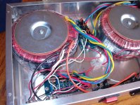
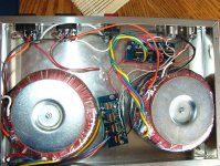
I'm not so proud of my power supply ... nevertheless see below pictures of the unit. Keep in mind this is my first electronics venture beyond fixing instrument cables.
The caps are indeed 10uf.
imperfectcircle said:"I'm using Peter's rectifier boards 1 per channel (1 xformer per channel also) with rather small caps on the boards (10uF Panasonic FC Capacitors)"
You are using only 10uf caps on the power supply boards?? This seems very small, I think a minimum of 1000uf would be more like it. Do you have pictures of the power supply??
I'm not so proud of my power supply ... nevertheless see below pictures of the unit. Keep in mind this is my first electronics venture beyond fixing instrument cables.
The caps are indeed 10uf.
Attachments
There are small caps by design on Peter's rectifier board. The main caps are on the amp board and they are 1,500 uF each. The unregulated design is intended to run with just that much capacitance. Matter of fact, I think that Peter runs just 100 uF Blackgates on his amp board...must sound very nice.
I don't know how you're measuring offset but yeah...you'll burn regular resistors like that. Why don't you just hook some piece'o'sh_t driver you might have laying about. That might be better and better resemble a real speaker.
Keep working it...
I don't know how you're measuring offset but yeah...you'll burn regular resistors like that. Why don't you just hook some piece'o'sh_t driver you might have laying about. That might be better and better resemble a real speaker.
Keep working it...
CarlosT said:Man...is that power supply fused?
Yeah, its fused, I've already popped two of them. The fuses are inside the AC receptacles.
Thanks for the tips CarlosT, it seems you're always somewhere nearby when I have questions.
do you know how I can get some more BASS?
I'm thinking more and more that it's just my speakers ... 15R with dome tweeters ...
Hey...I'm a noob so please don't take anything I say as if it came outta Mr. Jung's mouth
I do like to help people and I try to dabble in humility...two things that seem to lost on the lot here.
The only thing that comes to mind because you've got these Alps pots is that the chassis ground in the amp case may somehow need to be coupled to the chassis ground in the power supply case which is a true earth. Now I'm not a big advocate of earthing signal grounds because of noise and ground loop concerns but maybe the OOMPH just doesn't happen because the power supply ground is not hooked up to the signal ground and this messes with the functioning of the pots. Have you tried to make a jumper between the two cases to see if anything changes? It's just something to try...
Try a different set of speakers, too...
CarlosT said:Hey...I'm a noob so please don't take anything I say as if it came outta Mr. Jung's mouth
I do like to help people and I try to dabble in humility...two things that seem to lost on the lot here.
The only thing that comes to mind because you've got these Alps pots is that the chassis ground in the amp case may somehow need to be coupled to the chassis ground in the power supply case which is a true earth. Now I'm not a big advocate of earthing signal grounds because of noise and ground loop concerns but maybe the OOMPH just doesn't happen because the power supply ground is not hooked up to the signal ground and this messes with the functioning of the pots. Have you tried to make a jumper between the two cases to see if anything changes? It's just something to try...
Try a different set of speakers, too...
wikked , i will give that a try. thanks, it's nice to have someone to talk to around here
So you've got the bridge rectifiers followed by only 10uF of capacitance in one case, a power cord to transfer the unregulated DC to the amp case, and then 1500uF caps on each rail at the amp. Definitely try more capacitance directly after the bridge rectifier. I use 20,000uF after my rectifiers, a 4' run of cable to regulators which have 3900uF at the input, then some 120uF caps right next to the chip. No lack of bass and no overemphasized highs. Although my configuration is different from the standard NIGC, the power supply is still critical.
- Status
- This old topic is closed. If you want to reopen this topic, contact a moderator using the "Report Post" button.
- Home
- Amplifiers
- Chip Amps
- critique my amp layout please