Hi!
i am currently designing a simple headphone amp based on the TPA6120A2 chip for a university project.
As i am not experienced in this at all, i kindly ask you for suggestions, comments or mistakes i made.
I made the amp for balanced and unbalanced input, selectable with a simple switch, with a seperate pre-OPamp for the balanced part (thining about ths4032 here), protected from overvoltage by 2 schottky's. Power supply will be a simple stabilized 12V psu, divided by a TLE2426 rail splitter to get a clean supply voltage. i set the divided voltage to common ground; will this work??
I kept the signal path capacitor free and i'd like it to stay that way (if possible). For simplicity i use the 6120a2 in inverting config, afaik this should make no difference in sound quality...
I haven't set most resistor values yet, is there anything to take extra care about here?
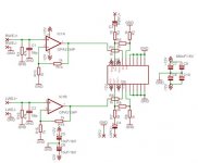
schematic:
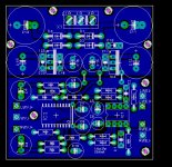
board:
I'd be glad to hear some feedback, maybe useful hints or mistakes i made; as i am a beginner in designing, every help will be greatly appreciated
i am currently designing a simple headphone amp based on the TPA6120A2 chip for a university project.
As i am not experienced in this at all, i kindly ask you for suggestions, comments or mistakes i made.
I made the amp for balanced and unbalanced input, selectable with a simple switch, with a seperate pre-OPamp for the balanced part (thining about ths4032 here), protected from overvoltage by 2 schottky's. Power supply will be a simple stabilized 12V psu, divided by a TLE2426 rail splitter to get a clean supply voltage. i set the divided voltage to common ground; will this work??
I kept the signal path capacitor free and i'd like it to stay that way (if possible). For simplicity i use the 6120a2 in inverting config, afaik this should make no difference in sound quality...
I haven't set most resistor values yet, is there anything to take extra care about here?
schematic:
An externally hosted image should be here but it was not working when we last tested it.
board:
An externally hosted image should be here but it was not working when we last tested it.
I'd be glad to hear some feedback, maybe useful hints or mistakes i made; as i am a beginner in designing, every help will be greatly appreciated
on the circuit:
I don’t think inverting operation is really suitable with audio sources ranging from Ohms to Kohms in output resistance – usually a noninverting buffer is used at the input to give a very high input impedance which keeps the gain independent of the source Z
Unbuffered inverting operation also requires a very low Ohm volume pot which will load most sources too heavily, particularly with your indicated 1 Kohm feedback R (which should probably be higher, ~2K to “overcompensate” the tpa – you probably don’t really want to peak its bandwidth to beyond 100 MHz)
further there is a absolute polarity convention – your amplifier shouldn’t invert unless you only use it with a source that inverts
quick layout comments
I see that you're using the usual default clearance for the top gnd pour - this is too tight, fringing field capacitance adds up quickly with too narrow a space
if you have 2 layers a much better gnd plane on the backside with few slots for routed traces is the way to go, the top side pour should be tied to the continuous backside ground plane with lots of vias to prevent them from becoming resonant antennas instead of shields
are you intending to solder the tpa’s pwrPad? - a largish single hole of ~ 1/2 the pwrPad dimension could let you get a solder iron tip and some solder under there manually - or you could reflow solder paste if you can avoid smearing and shorting the pins
the tpa's NC pins could be wired into the plane - probably help with heat sinking a little, and help keep the plane more intact
Thanks alot, jcx!
if i use the TPA in non-inverting configuration, will a buffer still be necessary?
i am beginning to see the problem with the pot; when i place it before the amp, i get trouble with my source; when i place it behind the amp i will get trouble with my amp.
What OP would one typically use for buffering? the OPA2134 indicated in TI's datasheet? I recently read some very positive comments about THS4032 amps; maybe i should go for that one... How about sound quality and buffers? i thought every additional opams would tend to colour the sound?
i will speak with my university's tutor about 2 layered boards, see if we can do that. for the cooling, we have a board mill / cutter (?) and an smd oven, so this will solder the TPA to the ground.
i will work on all this, after i got my exams done; which will be in a little more than a week..
Thank you,
greetings from germany
the tpa data sheet shows thermal distortion if you look carefully at the distortion plots with this in mind
so I think a better approach is Walt Jung's composite op amp circuits with the tpa inside the feedback loop:
http://waltjung.org/PDFs/Composite_Line_Driver_with_Low_Distortion.pdf
from http://waltjung.org/Classic_Articles.html
lots of useful reading for your application on the 2nd 1/2 of this page
so I think a better approach is Walt Jung's composite op amp circuits with the tpa inside the feedback loop:
http://waltjung.org/PDFs/Composite_Line_Driver_with_Low_Distortion.pdf
from http://waltjung.org/Classic_Articles.html
lots of useful reading for your application on the 2nd 1/2 of this page
thanks; got all this a little delayed, but i will begin actively working on this headphone amp in the next few days (i hope).
i redesigend the amp for noninverting configuration, after reading the TPAs evaluation modules manual. do i really need an input buffer? i am fine with a source-dependent gain, i wont switch the source often.
i am to keep the board single layered if possible, however if it really has to be a dual layer board, it would be possible.
how about the power supply? i am a little confused, will it work, if i use a 'normal' +12V psu, split the voltage with TLE2426 and connect the split output to gnd?
thanks for any comments and suggestions!
schematic+board:
An externally hosted image should be here but it was not working when we last tested it.
An externally hosted image should be here but it was not working when we last tested it.
- Status
- This old topic is closed. If you want to reopen this topic, contact a moderator using the "Report Post" button.
- Home
- Amplifiers
- Chip Amps
- Designing a simple TPA6120A2 Amp