In the last steps of finishing my first LM3875 GC.
1. I am aware that the two wires carrying the mains power are designated live and neutral, but is there any real difference in functionality between them? I placed a fuse in series with one of the wires and then realised that it's the one designated as neutral. Does it matter and should I change it?
2. In really easy steps could someone tell me how to wire a 10K linear potentiometer as a volume control? Does it go between the input from the cd player and the amp board. Since I have two input RCA's do I connect them together at the pot?
3. There are lots of opinions on earthing configurations. Has anyone created a step by step idiots guide as to what gets conected where, based on Brians kits?
4. My transformer output is in the form of three wires. Red, Orange and Black. The Red and the Orange provide @ 27 V each with respect to the Black wire. (54 V wrt each other) In Brians instructions I only need to connect these two wires to the rectifier and I have checked that this does indeed give me @ 38 V which I need. My question is...what do I do with the black wire if I don't need it.
Any input appreciated.
Thanks
Alan
According to Peter, the live and neutral configuration doesn't really make a diference.
There is a schematic and diagram for the wiring of a potentiometer in the instructions located on audiosector.com, which seems to be down at the moment.
It's on page 22.
If I'm understanding correctly, you have a center tapped transformer and am planning to use two of them to simulate dual secondaries. If this is the case, just shrinkwrap or otherwise isolate the unused wire. If you're planning to use the one transformer, then there's a wiring diagram in the instructions on Peter's site on page 15.
Hope this helps
hotscot said:...I am aware that the two wires carrying the mains power are designated live and neutral, but is there any real difference in functionality between them? I placed a fuse in series with one of the wires and then realised that it's the one designated as neutral. Does it matter and should I change it?
HUGE DIFFERENCE IN SAFETY!
The neutral (white) wires in the US are bonded (joined) to earth ground at the house breaker panel (you may also notice a ground rod buried deep right at the house meter or at the breaker panel strapped to the breaker panel). That means that technically contact between you and the white wires should not harm you. This is why the white wire is normally not switched or fused in house wiring. Of course, there are fault conditions in household wiring (reversed hot on neutral outlets, bad ground at the breaker panel, etc.) that may make this still a dangerous wire to touch but as a general guideline white = neutral = safe = grounded.
The hot (black) wire is a different story. If you come in contact with the black wire and you're also touching a ground object (faucet, another grounded appliance chassis, ground wire, white wire, wet ground, etc.), you could die...pretty simple. This is why the black wire is the one that's first fused and then switched.
I would certainly rewire your setup. The fuse will still go off in an overcurrent situation with your current setup but your chassis will remain unprotected and potentially hot as the black wire will still be part of the circuit.
hotscot said:...My transformer output is in the form of three wires. Red, Orange and Black. The Red and the Orange provide @ 27 V each with respect to the Black wire. (54 V wrt each other) In Brians instructions I only need to connect these two wires to the rectifier and I have checked that this does indeed give me @ 38 V which I need. My question is...what do I do with the black wire if I don't need it...
This doesn't make a lot of sense...
The black wire sounds like a common ground which you would then need to split into AC1 and AC2...
Do you have a diagram from the tranny manufacturer? It sounds like a center tapped single secondary tranny...the back wire is definitiely needed.
Without diagrams showing both the primary and secondary layout of the tranny, it's hard to help you here.
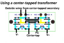
Center Tap Transformer
I don't have the schematic for the transformer handy but I've been working according to the attached diagram from Brian that shows two connections from the center tapped transformer to the rectifier board. It doesn't indicate using the center wire.
I have wired it like this and I am indeed getting plus and minus 38 V out of the rectifier board.
Regards
Alan
Attachments

Well for what it's worth, I've never suffered a significant injury from things exploding when I turn them on (and they sometimes do), and when you're working within a chassis, you have defeated the effect of grounding the exterior of the device. It's when working within that I find more accidents happen.
- Status
- This old topic is closed. If you want to reopen this topic, contact a moderator using the "Report Post" button.
- Home
- Amplifiers
- Chip Amps
- Four wiring questions