Hi all,
thanks for those who take the time to read these posts! I am building my first peter daniel gc. I have read many threads but still have some questions.
(1) Does the order of secondary connection to the rectifier board matter? Meaning 1 secondary pair goes to AC1 but it is not clear the difference between AC1 and AC1.
(Avel 250VA - Y236651)
(2) Where does the signal ground get connected on the amp board?
(3) Can someone describe the signal input and output connections on the amp board?
Thanks in advance.
Pathmark
Yes...the colors matter for the transformer hookup.
If I assume the usual dual primary/dual secondary setup for most Avel Lindbergs and if you live in the US (115V household power), the colors would be:
Primary (Parallel Hookup):
Blue and Purple Together - Hot AC Power (hot switch - black)
Grey and Brown Together - Neutral AC Power (white)
Secondary:
Black and Red Separate - AC1 and AC1 does not matter which AC1 hole you pick
Orange and Yellow - AC2 and AC2 does not matter which AC2 hole you pick
The tranny should have a clear layout of colors and phasing dots...keep going over these until you understand these. There are really good guides for the basics out there at the Hammond and Bicron websites among others.
BE CAREFUL!
Pathmark said:(1) Does the order of secondary connection to the rectifier board matter? Meaning 1 secondary pair goes to AC1 but it is not clear the difference between AC1 and AC1.
(Avel 250VA - Y236651)
(2) Where does the signal ground get connected on the amp board?
(3) Can someone describe the signal input and output connections on the amp board?
AC1 and AC2 do not require any order of connection, so it does not matter which pair of secondaries goes where, as long as they in proper pairs.
The signal ground gets connected to SG point on the amp board.
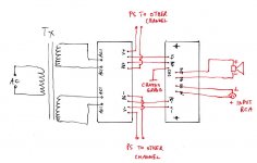
Attached is wiring diagram, as well some links that may be helpful:
http://www.diyaudio.com/forums/showthread.php?postid=787773#post787773
http://www.diyaudio.com/forums/showthread.php?postid=584425#post584425
http://audiosector.com/lm4780 psu.pdf
Attachments
Signal will be labeled
IN - input (signal +)
SG - input ground (signal ground)
Output will be labeled
OUT - output (output +)
OG - output ground (output ground)
Read over this document and see if you still have questions
http://www.audiosector.com/nigc_kit-users_guide.pdf
CHG is chassis ground
IN - input (signal +)
SG - input ground (signal ground)
Output will be labeled
OUT - output (output +)
OG - output ground (output ground)
Read over this document and see if you still have questions
http://www.audiosector.com/nigc_kit-users_guide.pdf
CHG is chassis ground
I have not worked with Peter's amp board but looking at it (got one right in front of me), it appears clear.
The bigger solder pads closest to the edge go:
V+ PG+ CHG PG- V-
A little further inboard you see:
OUT OG SG IN
These seem self-explanatory but yeah...I'm not sure either
V+ and PG+ are obviously the DC+ leads from the rectifier board
V- and PG- are the DC- leads from the rectifier board
OUT is positive output to your speaker or speaker binding posts or whatever
OG is output ground to your speaker or speaker binding posts
SG is signal ground...the ground input signal from your preamp or CD player or RCA input jacks
IN is signal positive input from your preamp or CD player or RCA input jacks
The only one I'm not sure about is CHG...maybe a common starground?
Peter...these PCBs are gorgeous! 
Any chance of you making a banked capacitor/LM338 regulated PSU board any time soon? That would just about round out your offerings.
Let's say 4 + 4 big caps/1 + 1 little caps banked right after the usual 8 MUR860s, some little bypass caps on the "adjust" leg of the regulator and some little tiny caps after the regulator plus all the usual resistor stuff.
Thanks!
Peter Daniel said:CHG is an additional ground connection, same as OG. It can be used for a chassis ground connection, or left unused.
Thanks, Peter. In my recent IGC, I left the chassis ground and amp board ground not tied together. I had a lot more noise when they were coupled as normal lore dictates. This might be the amp doing what it's supposed to do best I guess...AMPLIFY...even ground noise
- Status
- This old topic is closed. If you want to reopen this topic, contact a moderator using the "Report Post" button.
- Home
- Amplifiers
- Chip Amps
- Daniel LM3875 Assembly Help