Hi all,
finally getting my first project together - it's Peter Daniel's LM3875 kit and I am trying to do it as dual monoblocks.
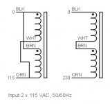
I have two transformers: Hammond 225 VA 60 Volts Centre tapped. From the Hammond pages (http://www.hammondmfg.com/182.htm and http://www.hammondmfg.com/5CHook.htm) I have determined that I need to connect the white and brown primaries, the remaining Black and Orange go to mains.
My question is this: there are 4 wires on the secondary side of the transformer. Where do I hook these wires to on Peter's power supply pcb? (reference: http://www.briangt.com/gallery/nigc-kit/build001). There are two spots labeled AC 1 and two labeled AC 2.
Do all 4 secondaries go to all 4 holes? Do I wire the transformer secondaries in series also and just run one side to AC 1 and one to AC 2?
Also, can I just connect ground from mains to the Aluminum case with no insulation (ie. this is the same metal I will touch to carry the amp)?
Thanks!
finally getting my first project together - it's Peter Daniel's LM3875 kit and I am trying to do it as dual monoblocks.
I have two transformers: Hammond 225 VA 60 Volts Centre tapped. From the Hammond pages (http://www.hammondmfg.com/182.htm and http://www.hammondmfg.com/5CHook.htm) I have determined that I need to connect the white and brown primaries, the remaining Black and Orange go to mains.
My question is this: there are 4 wires on the secondary side of the transformer. Where do I hook these wires to on Peter's power supply pcb? (reference: http://www.briangt.com/gallery/nigc-kit/build001). There are two spots labeled AC 1 and two labeled AC 2.
Do all 4 secondaries go to all 4 holes? Do I wire the transformer secondaries in series also and just run one side to AC 1 and one to AC 2?
Also, can I just connect ground from mains to the Aluminum case with no insulation (ie. this is the same metal I will touch to carry the amp)?
Thanks!
If I'm correct (I bought these outstanding kits, too), you should have two rectifier boards and two amp boards. If you're gonna use two trannies, why not use both rectifier boards?
You need to look at the schematic of the tranny to determine the pairs and the poles. I'm not familiar with the Hammond color schemes.
Grounding right to the case? Should not be a problem but there are a lotta other subtleties often brought up here like star grounding and disconnecting networks to cut down on ground noise.
meaghers said:I have two transformers: Hammond 225 VA 60 Volts Centre tapped. From the Hammond pages (http://www.hammondmfg.com/182.htm and http://www.hammondmfg.com/5CHook.htm) I have determined that I need to connect the white and brown primaries, the remaining Black and Orange go to mains.
My question is this: there are 4 wires on the secondary side of the transformer. Where do I hook these wires to on Peter's power supply pcb? (reference: http://www.briangt.com/gallery/nigc-kit/build001). There are two spots labeled AC 1 and two labeled AC 2.
Do all 4 secondaries go to all 4 holes? Do I wire the transformer secondaries in series also and just run one side to AC 1 and one to AC 2?
Also, can I just connect ground from mains to the Aluminum case with no insulation (ie. this is the same metal I will touch to carry the amp)?
2 x 30V AC is not particularly suitable voltage for GC amp. If you use each secondary separately, it will produce approx 43V after rectification and exceeds allowable voltage rating for those chips.
When you connect primaries in series (and that's the connection you mentioned here) you will be getting 22V DC after rectification, which is OK, although a bit low . However, the power from a transformer will be reduced when you run secondaries in series at half the voltage.
Anyway, all 4 secondaries connect to the board, and you keep them separate. Here's the wiring diagram, which also applies to LM3875 kit: http://audiosector.com/lm4780 psu.pdf
The Earth ground from mains can be connected to metal chassis. The chassis groung from the PCB (CHG) connects there too, through 10R resistor.
Peter:
I noticed the additional holes on your rectifier board for the "snubber" (gosh I wish I knew what that meant) setup components but your notes call for a minimum of 10,000 uF of capacitance. Does a 10,000 uF capacitor even fit on your rectifier board?
What is gained by going to a "snubber" setup?
Thanks!
I'm staring at some empty AudioSector rectifier boards right now as you may know
***My comments/questions are in reference to your LM3875 kit/recitifier board***
The bigger caps will fit the board as well, including compact size 10,000uF

I liked snubber initially: http://www.diyaudio.com/forums/showthread.php?s=&postid=550100&highlight=#post550100
Later however, I found some some defficiences that eventually put me off that aproach, which I'm not saying isn't good, it's just appeals to different tastes, the sound is less natural and more "manipulated". That's why none of my kits contains snubber components, however, the board still allows to use it:
http://www.diyaudio.com/forums/showthread.php?postid=574431#post574431
http://www.diyaudio.com/forums/showthread.php?postid=581230#post581230
Thanks, Peter...caps underneath the recitifier board...now why couldn't I think of that?
In the "less is more" school of thought, I'm listening to the Lm3875 combined-channel mono GC right now and the only capacitance is the 10 uF Panasonic FCs on the rectifier board and 1,000 uF Panasonic FMs on the amp board. Marvin Gaye sounds great
In the "less is more" school of thought, I'm listening to the Lm3875 combined-channel mono GC right now and the only capacitance is the 10 uF Panasonic FCs on the rectifier board and 1,000 uF Panasonic FMs on the amp board. Marvin Gaye sounds great
Re: Re: Easy question on Peter's lm3875 kit
I remember choosing this size xformer because of the example at the end of the 3875 datasheet. In the example they used a +-30V Transformer to get +-38.3V rectified and give 40W power with 8 ohm speakers. (see below)
I connected the transformer with the primary in series and all 4 secondary wired to one bridge and measured +-21.8V. This will only give ~20W according to the figure marked Output Power vs
Supply Voltage in the datasheet.
Am I understanding this correctly? If so, how can I get +-38.3V rectified from my transformer? I want 40 Watts ... don't I?
Thanks for your help Peter, and thanks for helping me get started in this way cool world of diy.
Peter Daniel said:
2 x 30V AC is not particularly suitable voltage for GC amp. If you use each secondary separately, it will produce approx 43V after rectification and exceeds allowable voltage rating for those chips.
I remember choosing this size xformer because of the example at the end of the 3875 datasheet. In the example they used a +-30V Transformer to get +-38.3V rectified and give 40W power with 8 ohm speakers. (see below)
An externally hosted image should be here but it was not working when we last tested it.
Peter Daniel said:
When you connect primaries in series (and that's the connection you mentioned here) you will be getting 22V DC after rectification, which is OK, although a bit low . However, the power from a transformer will be reduced when you run secondaries in series at half the voltage.
I connected the transformer with the primary in series and all 4 secondary wired to one bridge and measured +-21.8V. This will only give ~20W according to the figure marked Output Power vs
Supply Voltage in the datasheet.
Am I understanding this correctly? If so, how can I get +-38.3V rectified from my transformer? I want 40 Watts ... don't I?
Thanks for your help Peter, and thanks for helping me get started in this way cool world of diy.
Maybe the diagram below will be more clear; with 115V mains supply, the primaries should be connected in parallel. In that case your transformer will be producing +/- 44V DC, which is too high.
You need different transformer (2 x 25V AC or so), or keep it the primaries connected in series and have lower voltage and lower power, both from the amp and the transformer.
You need different transformer (2 x 25V AC or so), or keep it the primaries connected in series and have lower voltage and lower power, both from the amp and the transformer.
Attachments
- Status
- This old topic is closed. If you want to reopen this topic, contact a moderator using the "Report Post" button.
- Home
- Amplifiers
- Chip Amps
- Easy question on Peter's lm3875 kit