I would like to put together a single ended preamp with a couple of buffers (twisted pear and audiosector) and a attenuator (twisted pear joshua tree). I will be using this preamp with various chip amps.
my goal is to be able to switch the buffers and the attenuator in and out of the circuitry on a individual basis using toggle switches.
my preliminary schematic is as follows:
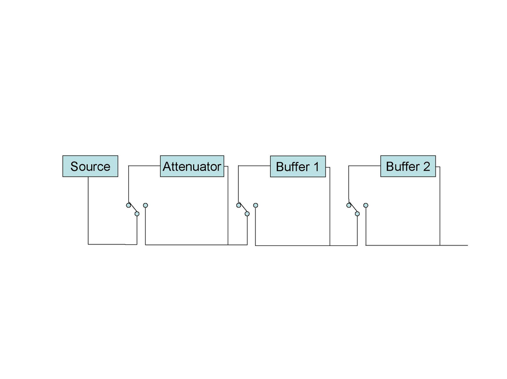
i have the following questions:
1. should the attenuator come before or after the buffers and why?
2. should the grounds also be switched?
3. should the devices be powered off when not in use?
4. is there a better way to achieve the same goal?
thank-you
my goal is to be able to switch the buffers and the attenuator in and out of the circuitry on a individual basis using toggle switches.
my preliminary schematic is as follows:
i have the following questions:
1. should the attenuator come before or after the buffers and why?
2. should the grounds also be switched?
3. should the devices be powered off when not in use?
4. is there a better way to achieve the same goal?
thank-you
1. yes - this way you can deal with signal input that exceeds the absolute max input voltage of the first buffer stage, as long as it doesnt exceed the power handling of your attenuator circuit (pot voltage divider?)
2. when possible, all circuit grounds should all be tied at a single point, 'star ground', to avoid voltage drops on bussed GNDs.
3. no - it saves power, but it adds complexity and thus degrades reliability, and the circuits behaviors at power up could pose to be a problem when switching to the device.
4. dunno looks okay.
k hope my opinions helped.
ren and nordic, thanks for your replies.
ren, in regards to question 1, Is it really a concern that a source, in my case a NAD cd player, could have a output that exceeds the max voltage of the buffer? I know this is a hard question for you to answer without having any knowledge of the buffers i will be using but i would have thought for safety sake that such a possibility would always be avoided when designing a buffer.
In terms of the power handling ability of the attenuator, the attenuator i will be using is a Joshua Tree is a logarithmic stepped attenuator with 128 steps. I'm not sure what it's power handling abilities are. i can tell you it uses .6 Watt 1% Metal Film Resistors. i think this is the relevant stat.
i'm with you on the powering up of devices being a problem (question 3), that was my concern as well. thanks for confirming it. i have a related question, should i be concerned about the output of one buffer arriving at the output of the other? to avoid this, i could use a multipole toggle that isolates the buffers (or attenuator) at the output as well as the input.
Nordic, i won't be using the buffers at the same time so the source or amps (depending on where i place the attenuator) will always see the changes is impedance associated with volume changes. However, I also believe i read somewhere on the twisted pear attenuator thread http://www.diyaudio.com/forums/showthread.php?postid=848119#post848119
that the output impedance does not vary much, i would assume that means the input does not vary much either but i'm not sure.
thanks again for your replies.
ren, in regards to question 1, Is it really a concern that a source, in my case a NAD cd player, could have a output that exceeds the max voltage of the buffer?
i wasnt thinking normal operation as much as fault conditions and having dynamic source abilities. typically diy audio stuff is experimented with to a degree, s#@! happens when youre playing with your gear.
if you trust the input source, id put an opamp as a voltage follower buffer as the first stage of your preamp. that way you can set the input impedance easily with an Rin resistor from +in to gnd, and its consistent regardless of youre switching after your input buffer. do to the simplicity and lack of parts, this is likely the least signal degrading circuit you can use as a buffer.
i have a related question, should i be concerned about the output of one buffer arriving at the output of the other?
most switches have dead time in them between the poles. you can hook the switch to a DMM and check for continuity, check to make sure theres at least a bit of travel before one pole disengages and the other engages.
Hi ren,
thanks for the help.
the switches do "break before make" so i'm in the clear there.
do you think it will be a problem when a buffer's input is switched off that it will still be powered up and potentially contributing to the output? i could avoid this by switching the output at the same time as the input for each buffer - is this a good idea?
i have a second more general question that relates to impedance matching. when choosing the order to place the attenuator and buffers, is the impedance the most important variable? If it is, should my goal be to match the output impedance of the source to the input of the preamp, and the output impedance of the preamp to the amp input impedance? Finally, if the impedance is not matching, is it better to have the preamp input impedance lower or higher than the source? The same question applies to the preamp output impedance in relation to the amps input impedance. i recognize that your comment about using a voltage follower may apply to this impedance matching question but i am relying on kits for this preamp because i don't have the skills to implement diy at the level .
.
for reference here are some of the impedance values i'll be dealing with. (i don't have them all in front of me right now)
joshua tree attenuator output impedance 750 ohm, input is variable
audio sector buffer output impedance is 6 ohm, don't know about the input
last but not least, i noticed on your thread that you're trained in cnc operation. i work in a very basic machine shop in my spare time and would like to further my training. can i ask where you went to school and how long it took to become proficient?
thanks for helping me out with all these beginner questions.
thanks for the help.
the switches do "break before make" so i'm in the clear there.
do you think it will be a problem when a buffer's input is switched off that it will still be powered up and potentially contributing to the output? i could avoid this by switching the output at the same time as the input for each buffer - is this a good idea?
i have a second more general question that relates to impedance matching. when choosing the order to place the attenuator and buffers, is the impedance the most important variable? If it is, should my goal be to match the output impedance of the source to the input of the preamp, and the output impedance of the preamp to the amp input impedance? Finally, if the impedance is not matching, is it better to have the preamp input impedance lower or higher than the source? The same question applies to the preamp output impedance in relation to the amps input impedance. i recognize that your comment about using a voltage follower may apply to this impedance matching question but i am relying on kits for this preamp because i don't have the skills to implement diy at the level
.for reference here are some of the impedance values i'll be dealing with. (i don't have them all in front of me right now)
joshua tree attenuator output impedance 750 ohm, input is variable
audio sector buffer output impedance is 6 ohm, don't know about the input
last but not least, i noticed on your thread that you're trained in cnc operation. i work in a very basic machine shop in my spare time and would like to further my training. can i ask where you went to school and how long it took to become proficient?
thanks for helping me out with all these beginner questions.
last but not least, i noticed on your thread that you're trained in cnc operation. i work in a very basic machine shop in my spare time and would like to further my training. can i ask where you went to school and how long it took to become proficient?
la community college district, pierce college. $22/unit, i think, this semester.
theyre tech AS degree, so like twice the major units, half the gen-ed as a liberal arts gen-ed AA degree. im taking two programs... so its like 4/5 major units, 1/5 gen ed (i think, no?)
its in north los angeles county, in the san fernando valley. there used to be alot of defence contractor stuff here in the 80s, so the machine and electronics teachers have alot of related experience in messed up high pressure work environments. (very practical)
ive been doing the machine stuff for maybe a year and a half now. im a lot better at the CNC/control/computer app side of it than i am the machining side. i was taking microprocessor asm and c++ programming the same semester as my first CNC classes, the CNC machines are alot easier to program than 8085 trainers.
and im always getting the hang of the metal maching more. its totally diff on a little NC machine than with the huge NC and manual mills and lathes at school. guess the hardest part is i need to learn to be more patient, most my scrapped parts are from rushing. little tiny open loop machine with no power helps with that. alot.
least you have a shop, tho... my little cnc lives in the corner of my bedroom =\ =\ =\
oh and dual pole/dual throw switches would be perfect for your application.
tie the same pole of both switches togther for bypass, and the other pole of one to the input of the buffer, the other pole of the second switch to the output. the common pins of the DPDT switch are the bypass/buffer circuits input/output.
this way, you wont have outputs fighting over levels on the bus, and you wont have unpredictable impedance issues from having multiple input resistances in parallel.
- Status
- This old topic is closed. If you want to reopen this topic, contact a moderator using the "Report Post" button.
- Home
- Amplifiers
- Chip Amps
- help with layout of multi-kit chip-amp pre-amp