Hi guys,
I am planning a Chipamp project right now. I would like to have your input on this.
The chip I'm am going to use is the LM3886.
I will be using this design for the amplifier part:
http://feuerbacher.net/DogBreath/Ch...ThreeResAmp.jpg
My problem is for the PSU part.
I already have bought three toroidal (it was an ultra good deal). They are going to drive 6 channels, two channels each. Here are their specs:
Dual 117/234 VAC primary, 50/60 Hz. operation. Secondary VAC. Hi-Pot test of 4,000V RMS between primary & secondary.
I don't really care what kind of PSU to use (snubber/regulated/etc...). I want a design that is cheap to build without compromising the sound. Why cheap? because it is going to drive the surround channels of my amp, and the quality is not crucial. And also because my amp is an 8 channels one and the whole system is starting to get pricey!
What do you pros think?
Jordan
Hi,
I suggest a rectifier and pair of smoothing caps to each amplfier.
+-10mF/ch might be a bit small, but then I'm a brute force type of builder. I hope you have 160VA to 200VA for each pair of channels.
8ohm speakers work well with +-20mF/ch, but if you are using narrow band speakers for most of the channels you may be able to trim this considerably.
Do you intend running wideband speakers for the front three channels or adding a sub-bass and running all other channels as narrow band?
The speakers that are wideband or bass only will need much capacitance, do not skimp here.
Oups I forgot to give the good specs for the toroids. They are : Secondary VAC (RMS): series: 20V + 20V @ 4A, parallel: 8A
4 of those channel will be used for the side left/right and rear left/right. The 2 remaining channel will be used like this: 1 for the front center, and 1 spare, in case one of them dies.
I am gonna be using the MyRef_C design for the 2 center channels, and the speakers they are gonna drive are suppose to provide enough bass, so I won't need a subwoofer.
Can you point me somewhere on the web to someone who made those type of PSU, and who gives a +/- precise howto or schematics?
Thanks for the help,
Jordan
http://sound.westhost.com/project04.htm
An externally hosted image should be here but it was not working when we last tested it.
Hi Jordan,
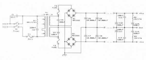
Notice that central (.) indicating the central audio ground.
ALL your grounds, power, signal, Zobel, decoupling, speaker, etc. must come to this point.
However, if the input grounds from two channels are brought to this central audio ground and then you connect an external source device that has it's two output RCA grounds connected together you will create a hum loop (earth loop).
You will need to add some resistance into the circuit to prevent the hum.
Cordell's interview gives an alternative hum buster (on the RCA input ground connections) that I have not tried. Worth trying.
There are certainly more complicated PSU designs out there like the wonderful article on TNT audio...
But the aim here is cheap and easy.
Also don't forget the very high PSSR of the overture chipamps... million to one area?
I have build this design before and its pretty good.
I have a little rule with ground wires... input RCA thinnest wire I have for the ground... output RCA ground thickest wire I can make fit.
But unless you have very high efficiency speakers this will still blow the socks off a $300 amp as a total package.
Yeah it looks strange but thats how its done for centre-tapped secondaries I think. They see 0VAC 25VAC and 50VAC with respect to the first wire on secondary.
Through rectification we made it +25vDC 0VDC and -25vDC
The two extreme potentials are still 50V appart!
(imagining 1:1 conversion for sake of simplicity)
For seperate secondaries you could steal your concept from this circuit ,do not loose earth disconnect network from previous schematic... THIS IS THE FIRST THING YOU PUT IN ANY AMP, AS LONG AS YOU REMEMBER ME.
I will attach eagle files for you, to make one.
Attachments
")
The big caps are to filter ripple from the power supply rails. The diodes in the bridge only conducts power during a small part of the AC wave, be it 50 or 60hz. The caps maintain the voltage on the rail during those non-conducting moments, and will of course help to supply current when there is a a sudden transient demand.
With the low part number PSUs the lower ESR caps you can get (read most expensive) will be money well spend. Sometimes paralleling 2 smaller caps will give you lower ESR than using a single cap, twice their value... this is good...
15000uf is enough for about 50W into 8 ohms on a pure joules storage basis..., so 2 x 10000, or 4 x 4700, is allready a little overkill.
- Status
- This old topic is closed. If you want to reopen this topic, contact a moderator using the "Report Post" button.
- Home
- Amplifiers
- Chip Amps
- And now the PSU hmm...