Hi, I wonder why nobody has not talk about this configuration taken from LM338 datasheet...
LM307 is discounted but I think LF411 can be used instead...
Any ideas about this regulator? 15 A on each rail seem quite enough for a gainclone
An externally hosted image should be here but it was not working when we last tested it.
LM307 is discounted but I think LF411 can be used instead...
Any ideas about this regulator? 15 A on each rail seem quite enough for a gainclone
Member
Joined 2003
Hmm... 6 LM338 ICs (3 per rail) would take up a lot of PCB space when considering the size of some PCBs made for the LM3886, and I'm sure they'll require heatsinking of some sort. Would make for a fun experiment to try out. Are you planning to construct this regulator ans try it on an amp?
I hate that word....Gainclone...I especially hate it when the word is used to describe something that shares no similarity to the Gaincard except that it uses the same amp IC.
I hate that word....Gainclone...I especially hate it when the word is used to describe something that shares no similarity to the Gaincard except that it uses the same amp IC.
DcibeL said:Hmm... 6 LM338 ICs (3 per rail) would take up a lot of PCB space when considering the size of some PCBs made for the LM3886, and I'm sure they'll require heatsinking of some sort. Would make for a fun experiment to try out. Are you planning to construct this regulator ans try it on an amp?
I hate that word....Gainclone...I especially hate it when the word is used to describe something that shares no similarity to the Gaincard except that it uses the same amp IC.
Completely right
I apologise for using the word "Gainclone", I should have used "ChipAmp" Yes, I am planning to build this regulator as it is relatively simple than any other high current regulators. I am thinking bi-amping but I still don't sure about which chipamp to build
Maybe Mauro's my_ref C..peranders said:Only one LM338 is probably sufficient but min d though that you need to separate windings becuase you'll use two positive regulators.
Check digi01's design.
I know, It will look like the regulated power supply of Carlosfm ; I will just replace the single lm388 with the circuit above...
I don't want the power supply to limit the sound that's why I looking for something more powerful than single lm338
MaxS said:Hello,
You'll have a look at LT 1083 ( 7,5 A ), it would be a good thing.
Thanks, I will consider them for future projects however I already have some lm338s in my hand.
AndrewT said:Hi,
why are you considering regulation and chipamp?
That seems to defy the simplicity that chipamp brings.
Plain, ordinary rectifier/smoothing caps suffice.
Or, go brute force and fit VA=2*power output & smoothing @ +-20mF/channel
I came across with chipamps a couple of months ago. Since then I was searching nihgt and day
At first, I decided to built an unregulated one but then I red that the regulated is much better and I decide to build a regulated one... Somes says switching is even better than regulated one but I don't like switching psu. Actually, I am not interested in simplicity much. My real goal is the sound quality. I have give up from buying a Creek Destiny amp. after coming across with chipamps. Therefore I want to make a chipamp which should sound at least as Creek Destiny does.
Another option is a pass transistor regulator like the type discussed here
I'm not sure how it compares in the audiophile world, but in my world it turned out to work very well.
Right now I'm using one 2n3055 per rail. I guess I could have just used a single LM388 per rail, but this was a lot more fun and I learned a few things in the process.
Pics of the supply powering a class-d amp at +-35v......
http://i11.tinypic.com/2exshz8.jpg
http://i11.tinypic.com/2hdmflg.jpg
Thanks theAnonymous1, Your supply seems good but I don't want to go with discreets at now..
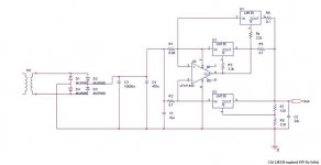
Here is the basic version of the circuit.. Voltage drop along the whole regulator is about 3 volts in this configuration and capable of giving more than 30 Volts according to Pspice simulations...
Here is the basic version of the circuit.. Voltage drop along the whole regulator is about 3 volts in this configuration and capable of giving more than 30 Volts according to Pspice simulations...
Attachments
hi seftali,
If you build this and really want the 15A capacity, remember to size the heatsinks properly.
The minimum case at 15A with a voltage drop of 3V gives 45W. If you use a transformer that requires, say, 6V to be dropped across the regulator then that's 90W.
BTW: A chipamp won't draw 15A for vey long (because it would only draw this much current under fault conditions)
regards

Dxvideo said:15A is very big current for me.. But i have a question; how could you find MUR860s in Turkey? Did you purchase them from an on-line store?
PS: I am surprised to find another Turkish member in DIY Audio forums!
Hi, It's very nice to see another Turkish member here
It is almost impossible to find specific electronic components in Turkey, I have bought them directly from On Semiconductor web site.. If you are interested, with a couple of friends, we'll buy some components form an online-store to share the shipping cost. You can send a mail..15A is a big current indeed, but actually It's capable of giving 15A current and It will provide much less current in normal listening. So I don't see any problem in using a high-current supply.
cjd said:Might want to step beyond MUR860's...
I am thinking of some IXYS fast-recovery bridge rectifiers for the future

peranders said:Only one LM338 is probably sufficient but min d though that you need to separate windings becuase you'll use two positive regulators.
I made a horrible mistake and bought a 26-0-26 V toroid

Hi,
Sorry to re-open the thread 7 years later, did someone tryed this psu ?
I would try to improve it a bit, with my poor knowledge, and lot of feeling.
Why not using 1 op amp for each slave regulator so that there's no more need of output balancing resistor, and raising impedance so much lower ...? It would need to put the same input resistance for each 3 regulator...let say 0,05ohm each. It seem to be a cheap solution with ld1084 instead of lm138 and with ad712 as dual op amp. And supply voltage of the op amp need decoupling, and so should be taken before the resistors...
LM138 allow by itself 12A transient, so x3 =36A, wich could be a lot too much. Ld1084 is a ldo, and is current limited at 7A so 21A for 3.
And a common mode cheap inductor after rectifier should help reducing diode switching hamonics (cheap => high resistance=> protect from high current demand from capacitor bank).
To me this design seems simple and cheap, adding power and thermal protection for high power.
Does what i'm talking about make sense ?
Thanks,
Damien
- Status
- This old topic is closed. If you want to reopen this topic, contact a moderator using the "Report Post" button.
- Home
- Amplifiers
- Chip Amps
- 15 A Voltage Regulator with lm338