Hi,
I've finished the LM3886 chipamp/snubber dual mono
pcb. I'm using one transformer and two snubber boards
to each LM3886 pcb.
Upon power up, everthing is fine until I connect
the RCA cables from my preamp to the LM3886 inputs, it
buzzes like crazy. No connection at the input, no buzz.
This Buzzing noise is oscillation?
I'm using mogami 2534 for the interconnects. One
channel is about 3.5" long and the other is about 1.5"
from the pcb to the rca connector. I'm not using the shield,
just the twister pairs for + and GND.
Do I need to add a resistor between the + and GND
at the RCA connector?
I'm also using the Ci 47uF cap if that makes any difference.
It did lower the dc voltage to about 1mV for each channel.
Now only if I can get pass this buzzing problem...
Thanks.
I have also found that if I disconnect the rca cable from one channel the buzzing goes away. If both Left and Right channels are connected, it will buzz.
The buzzing always comes from the same channel.
Now, I tried with just one channel, playing back a cd source, the volume level is low and distorted even if I turn it up.
I would appreciate your input. Thanks.
The buzzing always comes from the same channel.
Now, I tried with just one channel, playing back a cd source, the volume level is low and distorted even if I turn it up.
I would appreciate your input. Thanks.
Sorry..actually red your text. You need balanced audio. This means:
1. You must have a + , a -, and a Ground/Earth. You cannot have just a positive and ground to be considered balanced audio. This is more than likely the cause of your buzz due to interference.
Look it up. An Example.
One major difference with balance audio and unbalanced is the difference between a TRS(tip ring sleeve) and a TS jack(tip sleeve). TS quarter inch jacks are your common instrument cable jacks(bass, guitar) that plug into their specified amplifier cabinets. For amplifier audio that involves speaker output, you need a TRS jack. Tip positive, ring negative, sleeve ground.
thanks. I will try standard coax rca cable instead and see what happens. The mogami 2534 has 2 twisted pairs and a shield.
I've tied the blue pair to positive and the white pair to (-) plus the shield as rca interconnects on my off the shelf equipment, no problems here.
I just did not use the shielding between the LM3886 pcb and the rca jack. I guess I could try using the shielding as well to the (-).
One of the channels is highly distorted and has no volume.
I guess the chip is defective. Will have to replace that one as well. not much luck so far.
Hi Bengali,
I have a similar set up, are they the chipamp boards per chance? If so have you connected the CHG of each board to the other? I found that when I used a thick copper cable between them and kept its length as short as possible it massively reduces the buzz/hum.
Cheers,
Ian
I have a similar set up, are they the chipamp boards per chance? If so have you connected the CHG of each board to the other? I found that when I used a thick copper cable between them and kept its length as short as possible it massively reduces the buzz/hum.
Cheers,
Ian
Hi,
sounds like an earth loop is completed when the shields from the two RCAs connect.
The problem is that the chipamps each have their own central ground and these central grounds are connected, probably to safety earth.
You cannot expect ALL your source equipment to have isolated RCA grounds. So, you must isolate the grounds in the power amp.
The very short, thick wire between the chipamp central grounds attenuates the problem but does not eliminate it.
Can you provide an annotated pic of the internals or a layout drawing of the physical relationship between the various components inside the amp.
ianpengelly said:Andrew,
What would be your proposal for isolating the grounds in the power amp? If I remove the ground wire connecting the two boards the problem gets worse, yet the grounds are effectively isolated?!
Ian
Just to make sure, I think what Andrew means is that the RCA barrel should be insulated from touching the chassis, and thus connecting the input ground directly to safety earth. The RCA connectors should come with a sort of.. plastic washer to do this.
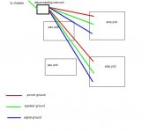
For what it's worth, attached is a picture of the grounding scheme that has worked for me, but I have totally separated the ground traces on my PCB (that is, on the amp PCB's there is no trace connecting power ground, speaker ground and input ground together).
My signal ground and speaker ground from the connectors actually go back to the PCB, then I take the trace they connect to back to the disconnecting network as shown in the picture. Andrew has advised me to just take these connector grounds from the connectors straight back to the disconnecting network separately instead of the PCB, but... it's working fine, so I haven't got around to doing this. You know how it is!
")
Attachments
Hi Ian,
seems like a similar, but slightly different problem.
Put a multimeter set to low ohms between the input RCA barrels.
does it read less than 1ohm?
If so, you have an internal half loop.
Connect an external half loop and you will get hum and/or buzz.
All those wires running to the disconnecting network are not needed.
Your layout would suit a central star ground (audio ground) right in the middle of the group of four. Then run a single wire from audio ground to disconnecting network.
Beng,
have you connected the audio ground to the common wire/plate between the smoothing caps?
Then that is probably the source of the buzz rather than the hum.
Have you connected the mains safety earth to chassis?
Have you connected chassis to any part or parts of the audio ground system?
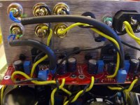
Thanks for your help. Here is a pic of how things are connected. I have the Earth Gnd from the IEC Jack bolted to a screw along with the 2 (CH)assis points on the LM3886 pcb's.
The mogami cable, the blue wires are tied together for the positive and the white to gnd terminals of the rca jacks.
the snubber pcb power wires goes directly to the lm3886 pcb's.
speaker output goes directly to the banana jacks.
I measure about 46K between the rca jack's positive terminals.
From the feedback, I should connect the power,signal,speaker gnds all to the same point(?) If this is the case, then I would need to remove the isolation from the (-) terminals of the rca and speaker jack?
thx.
Attachments
As long as everything that has a ground (includeing the pcb ground points), is grounded separately and the + and - are very short wires(to cause less interference), i dont see too much of a problem. I don't have too much experience with chip amps though so i don't quite know their grounding procedure
here's the latest. one channel sound really distorted and the low volume remained the same even if I turn the preamp volume up.
I swapped out the chip, made no difference. I then swapped out the pwr and Ci caps. The audio is now normal. after testing it again, without the top chassis on, even with both rca connected to the inputs, No buzzing.
I then put the top cover back on, powered everything back up, heard audio for about 10 seconds, then it's back to the low volume distorted sound again.
I'm starting to wonder if my chassis is just too small, everything is crammed to tightly, and when the top cover is on, something bad is going on.
My next testing will be done without a preamp, all I have is a 100K pot, will that work or do I really need to get a 10K pot?
thanks.
Bengali said:here's the latest. one channel sound really distorted and the low volume remained the same even if I turn the preamp volume up.
I swapped out the chip, made no difference. I then swapped out the pwr and Ci caps. The audio is now normal. after testing it again, without the top chassis on, even with both rca connected to the inputs, No buzzing.
I then put the top cover back on, powered everything back up, heard audio for about 10 seconds, then it's back to the low volume distorted sound again.
I'm starting to wonder if my chassis is just too small, everything is crammed to tightly, and when the top cover is on, something bad is going on.
My next testing will be done without a preamp, all I have is a 100K pot, will that work or do I really need to get a 10K pot?
thanks.
Unless something is shorting, or opening, or heating too much with the case on:
Can you check those caps more closely? Can you measure the DC and AC voltages across them, while operating? And then maybe replace them again and try to get the same measurements while they are operating correctly. Can you test the ones you removed to see if/how they failed? Do you have an ESR (Equivalent Series Resistance) Meter? (Or, if you have an oscilloscope and a square wave generator, you can use this, instead: http://www.fullnet.com/~tomg/esrscope.htm .)
- Tom Gootee
AndrewT said:Hi Ian,
seems like a similar, but slightly different problem.
Put a multimeter set to low ohms between the input RCA barrels.
does it read less than 1ohm?
If so, you have an internal half loop.
Connect an external half loop and you will get hum and/or buzz.
Andrew, I finally got around to doing your little test and there is practically zero resistance between the RCA barrels. Would it be possible to use one transformer winding per channel and remove the chassis ground connection, thereby, removing all physical connections between the amps (as if they were true mono blocks) and hopefully the internal loop?
Hi,
as a very temporary experiment, you could disconnect the chassis from the audio grounds on one channel. Then couple up and test with a stereo audio signal. If it is hum free then it comfirms that an earth loop is the problem.
BUT, you must reinstate the safety earth to audio ground connection BEFORE you put this amp to work.
I'll try that, but in answer to my main question is it possible to use 1 primary per rectifier, i.e. split one primary so that it provides both the +ve and -ve feeds to the amplifier board?
I guess the equivalent would be trying to use a transformer with only one secondary winding to power a mono amp.
Cheers,
Ian
I guess the equivalent would be trying to use a transformer with only one secondary winding to power a mono amp.
Cheers,
Ian
Hi,
using a bridge rectifier on a single secondary will give you a full wave rectified single polarity supply i.e. V+ & 0V.
Two half wave rectifiers can give dual polarity supplies but one should try to balance currents in the two halves, particularly with toroids.
You cannot get dual polarity supplies from full wave rectification (single bridge) and single secondary.
If you build two monoblocks inside a common housing then each monoblock needs it's own disconnecting network to safety earth to make the whole amplifier safe to use and isolate each half sufficiently to prevent a hum loop.
- Status
- This old topic is closed. If you want to reopen this topic, contact a moderator using the "Report Post" button.
- Home
- Amplifiers
- Chip Amps
- LM3886 Buzzing