
Stanley Drake said:I do not need such comments about schematics
I just need to know DOES MY PCB ROUTING OK OR NOT
There are already 11 posts and no one obout my PCB. Only flood
Please someone tell me something about my PCB
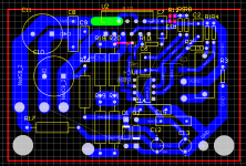
Here is updated PCB
I have not looked very closely at it, but my first impression is that the routing looks fine. It may be time just to etch one and give it a try.
")
Please do not forget the DC protection (as you said) as you will need it.
Good luck!
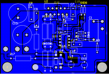
Stanley Drake said:Does this long wire at the right edge ok?
Well, no. It is too long, that is a feedback net.
I mean it would likely work, but it is not optimal.
AndrewT said:Hi,
is the 3886 allowed to run at low gain?
You seem to have 47k (R7) into 22k (R14) giving -7db.
Does R10+C7 compensate?
This is an interesting variation, it is used as a differencial amp woth close to zero dB gain having the mojority gain (30 dB) from the pre-amp.
I am not sure what the purpose of the parallel series 0.47 ohm at the output where one feedback circuit is before and the other after the network.
I would say if both feedbacks should be after the resistive ladder unless this somehow adjusts the off-set.
Stanley Drake said:I do not need such comments about schematics
I just need to know DOES MY PCB ROUTING OK OR NOT
There are already 11 posts and no one obout my PCB. Only flood
Please someone tell me something about my PCB
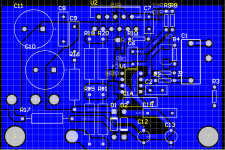
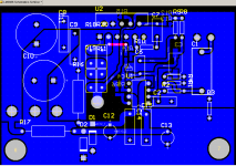
Here is updated PCB
Appart from checking the circuit against the layout(which Protel should do automatically) I think the layout is fine. Even your long feed-back wire is in reality not that long, it is quite short so I would not worry about that too much.
If hole 7 represents the head of a screw, it is fine, but if this is the size of the hole then the head of the screw will short the feed-back to ground once tightened.
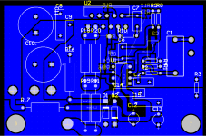
Interesting mix of SMT and conventional components, I have no problem just first time I see this on the forum.
The fact of the matter is you have everything on board, you may as well place the recitifier diodes on the board to, there is more than ample space.
Earth plane is good, it ensures low impenance for all the connections.
One otehr comment, I do not like the Chip being the support for the PCB at the back. After a few bends, when installing, you will lose some lengs. Provide for mounting at the back of the board as well. It may be a better way even to secure the heatsing to the PCB with some L shape brackets, then it is a unit and the heatsing will not wobble while testing is done outside the box.
Kind regards
Nico
I have made shorter feddback network. Now it seems everything ok. Tomorrow I will etch and solder PCB.
Yes hole 7 and 6 have diameter of screw head.
Firstly I was going to make whole board from SMD but when I started to rout it was insane to rout it on one layer.
Rectifier bridge and 2x22000uF capacitors I already have on separate PCB. And I have a complete chasis with mounted power supply, DC protection, and transformer. Just need to instal amplifier PCBs.
I think L shape brackets are overkill and 2 support points will be quite enought
I use parallel series 0.47R because I haven't found non-wirewound power resistor.
Thanks for help
Attachments
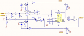
Stanley Drake said:and schematics:
Dear Stanley,
I am making a general observation that since most of the gain of the amplifier system is contained in the LM318. You are driving this op amp only from 12 V, which means that the output cannot swing more than 10V (Vsupp -2V acording to the data sheet).
Since the main amp has slightly less than unity gain means that you will never achieve full output since your output voltage would be only ±10V translating into an RMS power of 17 watt into 8 Ohms. Is this what you are after, also keep in mind that the OP-AMP will start to clip at this point and a about 15 watt rms is more likely.
To get more power from your system either run the op-amp at closer to ±20V or add soem gain to the main amp, only 6 dB or so would be sufficient.
Kind regards
Nico
- Status
- This old topic is closed. If you want to reopen this topic, contact a moderator using the "Report Post" button.
- Home
- Amplifiers
- Chip Amps
- My Version of Mauro Penasa's LM3886