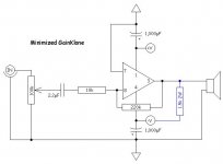
So, whats the problem. Ive made gainclone with mentioned chip.Ive connected all as on scheme is, but that scheme was total minimised gainclone, which means no 100nF caps included at positive and negative rail.
+ and - voltage after greatz bridge and caps is 40.2V, which is 80.4V total.
So ive connected speaker on amp and suddenly it was burnt.Chip was very hot. The DC voltage was disaster and breaktrough in chip happened (resistance between -Vcc and GND is about 0.5 Ohm)
1.How have i burnt everything, if voltage was ok and connections were OK?
2.What *must* you do, to get DC voltage/chip breaktrough/big voltage at amp output (the most common mistakes)?
Attachments
The Gainclone is allready Minimalized so why would you want to make it even more Minimal?? You are just asking for trouble because the Things you have Omited from the design are There for a reason Like to prevent Oscilation and for the Chip to run Stable and to prevent DC Offset....
You should go back and look at the Data sheet and and rebuild the Chipamp properly as per the Datasheet .....
I think what is happeneing is the Chip is Oscilateing which is caueseing it to quickly overheat and causing huge DC Offset, also you are running at close to the Max Voltages that the Chip can handle so you had better have a Big heatsink also the 100K Pot at the Input is too big ,It should be 10k to 50k max I think...
You should also add the 0.1uF caps to the supply pins close to the IC and add a 1k resistor in series with the 22uF Cap to ground off of Pin 8 and add a 220K resistor from the input to ground so there is a Path for DC to leak to ground and maybe sure you have enough Filtering in your Powersupply (at least 4700uF per rail per Chip)
You should be able to do these things without much trouble and it should solve yer problems....
Good Luck
PS: I hope Grandma doesn"t Punnish you to badly for screwing up her Chip amp...
moamps said:Are you sure you insulated the chip's tab from the heat sink mass?
Regards,
Milan
Sure.The Ohm-meter has shown infinitive resitance.
In that case, your amp may have run into oscillation, which is not entirely unusual for amps working in the inverted mode. Next time, you may wish to test the amp first by connecting it to a resistor. Once you're positive everything is fine, you can hook up your speakers.
Regards,
Milan
Regards,
Milan
MikeW said:Why are you biasing the output? after the feedback resistor you need to have a resistor to ground or you will have infinite gain. The output will go to the rail.
You mean this (take a look at attachment)?
jackinnj said:When you force an amplifier into Class-A all sorts of nasty things happen -- you might just as well have turned it into a space-heater.
You are talking about that 1.5k/2W resistor?I didnt include it in my project.
And the most important; that scheme isnt my work, ive found it somewhere on the net.
Attachments
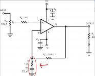
And why there is no connection between GND and feedback resistor in NUUK´s design?
An externally hosted image should be here but it was not working when we last tested it.
Grandma´s_SUB said:This is like u build a house and say "Maybe it will collapse"...
If you had no architecture experience or building skills, it may well do so!

if a learner bricklayer can make a mistake that burns down the house.....even they use a level.
If you make no mistakes, and don't try to drive 4ohm speakers and have sufficient heatsink, you will trip the mains, not destroy the amp.
One solder splash in the wrong place and you could try to push PSU voltage x gain through the chip.
If you look at the brown amp in the gallery.. it has exactly that circuit in.
Heh, the "hack" is that test circut worked, but with PC power supply.Then I added my PSU (40.2V) and hell happened. First speaker has sung some buzzing then after few secs it burnt.It was like "wth?"...There were no smoke signals, just PSU supply voltage at output and big current which happened because of voltage breaktrough in chip, I think.
So I will ask again; How can breaktrough in chip happen, since PSU voltage isnt larger than recommened?
So I will ask again; How can breaktrough in chip happen, since PSU voltage isnt larger than recommened?
Grandma´s_SUB said:Heh, the "hack" is that test circut worked, but with PC power supply.Then I added my PSU (40.2V) and hell happened. First speaker has sung some buzzing then after few secs it burnt.It was like "wth?"...There were no smoke signals, just PSU supply voltage at output and big current which happened because of voltage breaktrough in chip, I think.
So I will ask again; How can breaktrough in chip happen, since PSU voltage isnt larger than recommened?
From looking at the First Schematic you posted it looks like you have the Negitive voltage connected to the output through the 1.5k 2w resistor which is Just going to put -40vdc (Minus resistor Voltage Drop) directly into the Speaker which will fry it pretty damn quickly unless I am reading it incorrectly....
It seems who ever designed that schematic didn"t really know what they were doing or didn"t test it......
The Chip might not be Burnt out but your speaker Might be, I suggest that you rebuld it as per the Datasheet and try it and if it doesn"t work put in a new Chip.....
There are a Lot of reasons why the design is flawed and it is easy to fix....
Grandma´s_SUB said:So I will ask again; How can breaktrough in chip happen, since PSU voltage isnt larger than recommened?
Hi Grandma,
Assume:
1. Nuuk's schematic is correct. (with 4.7uF input cap). Thousands have been successfully built.
2. The LM3875 chip is nearly 100% realiable.
Now, what have you done wrong? Can you post the schematic of the PSU you used? Have you connected th 0V correctly? I have found on some amps (can't remember about GCs) if you leave off the 0V wire you get full voltage on the output.
As mentioned before, ALWAYS check DC voltage on speaker posts before connecting speakers after you have made any changes to you circuit. A value of 100mV or less will cause no damage.
regards
- Status
- This old topic is closed. If you want to reopen this topic, contact a moderator using the "Report Post" button.
- Home
- Amplifiers
- Chip Amps
- LM3875 troubleshooting