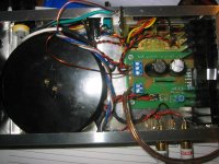
Well I've pestered all yous enough that I thought you at least deserved a look at the first test mule. Thanks to all and especially Pinkmouse, AndrewT, Nordic, Peter Daniel, V-Bro and others.
I'm running a gain of 58 right now (R2 = 140K, R1 = 2.41K [effective with summing resistors added in]) and a simple non-polar 6.8uF cap on the input to block DC. Sounded pretty bad with a substandard MP3 player but sounds wonderful hooked to my PC ight now with Rhapsody playing.
I'm thinking of turning the gain down a little still but the real test is hooking up an iPod to it.
Any thoughts...comments?
Attachments
Al:
Thanks! There's a 1K resistor soldered inline with each input and shrinktaped in the braided wires...can't see it...stealth
Yeah...overall pretty loud.
One last concern is grounding. This is a favorite of AndrewT but I'll entertain anyone's thoughts here.
Let's say that there's a star ground point right where the power supply DC commons enter the amp PCB. At this point we will have effectively and directly joined:
1- input grounds (let's assume that these are isolated from the chassis at the point of entry into the chassis)
2- power supply DC commons grounds from the rectifier board
3- pilot light ground
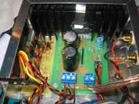
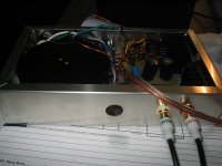
The question is why does one need to join this star point to the mains AC ground/chassis bonding point? If you look at the pics, I have this crazy piece of magnet wire joining the amp star ground and clipped to the chassis and mains AC ground but this is causing a lotta noise when my laser printer prints for example or when I switch my desklamp on and off. Removing the ground instantly quiets the amp in all states.
To AndrewT this is a safety issue but he brought up some obscure instance where the input grounds coming from another appliance where somehow hot due to some improper grounding or hot lead contact at the other appliance. This is not an issue here because the input device is a battery-powered MP3 player or at worse a laptop's headphone jack.
Is there a happy medium? Can the mains AC ground be bonded to the chassis for safety but yet not connected to the amp board's star ground? I've seen so many schematics on this forum where there is a conduit between the AC ground starpoint and the amp's ground starpoint but I guess I don't get it still.
Thanks! There's a 1K resistor soldered inline with each input and shrinktaped in the braided wires...can't see it...stealth
Yeah...overall pretty loud.
One last concern is grounding. This is a favorite of AndrewT but I'll entertain anyone's thoughts here.
Let's say that there's a star ground point right where the power supply DC commons enter the amp PCB. At this point we will have effectively and directly joined:
1- input grounds (let's assume that these are isolated from the chassis at the point of entry into the chassis)
2- power supply DC commons grounds from the rectifier board
3- pilot light ground
The question is why does one need to join this star point to the mains AC ground/chassis bonding point? If you look at the pics, I have this crazy piece of magnet wire joining the amp star ground and clipped to the chassis and mains AC ground but this is causing a lotta noise when my laser printer prints for example or when I switch my desklamp on and off. Removing the ground instantly quiets the amp in all states.
To AndrewT this is a safety issue but he brought up some obscure instance where the input grounds coming from another appliance where somehow hot due to some improper grounding or hot lead contact at the other appliance. This is not an issue here because the input device is a battery-powered MP3 player or at worse a laptop's headphone jack.
Is there a happy medium? Can the mains AC ground be bonded to the chassis for safety but yet not connected to the amp board's star ground? I've seen so many schematics on this forum where there is a conduit between the AC ground starpoint and the amp's ground starpoint but I guess I don't get it still.
One minor question...electrolytics in the input path. Since I'm running such little resistor values in the R2/R3 positions in order to get the gain nice and high, this also prompted some pretty high values for the C1 input DC blocking cap. I scrounged and came up with some little Xicon non-polar electrolytics 6.8uF (see the little light blue cap in the pics). I have read that this is audio poo poo...using electrolytics in the input path. The little amp sounds OK overall but what do you think? Should I strive to use a metallized film cap in this position?
pinkmouse said:...I'm with Minion, if you can reduce the gain once you know the output of the iPod, then it would be much quieter.
I figured that the iPods put out about .5 V so in order to the get the full juice outta the 30V power supply feeding the LM3875, the calculation would be 30 divided over .5 or about 60. However, I think that this is a bit much. I'm running what I think is a gain of 58 now and the bass is a touch...not boomy...but pronounced and a subpar MP3 player I tried was just plain clipping and overheating the little thing it seemed.
Minion you mentioned going from 47 to 22...that sounds like a big step yet you said that the volume was still acceptable. I was thinking of maybe going to 50 or 40.
- Status
- This old topic is closed. If you want to reopen this topic, contact a moderator using the "Report Post" button.
- Home
- Amplifiers
- Chip Amps
- Test Mule # 1 IGC Mono Boombox Amp