CarlosT said:
Right now each V+ and V- bank has a 10 uF electrolytic cap at the rectifier board and a 1,000 uF electrolytic cap at the amp board.
I just did not understand the function of a cap across V- and V+.
Carlos is this statement correct, the resevoir cap, the one near the recifiers should be the largest.
If the series transistor turns on it will swing high very rapidly and if the largerof the two capacitors is at the output of the regulator this would look like an instantaneous short circuit that could move the series transistor out of its Safe Operating Area.
It may be wise to put a 1000 uF at the recitfier end as well.
If I misunderstood you then I apologise.
Kind regards
Nico
Nico Ras said:
... the resevoir cap, the one near the recifiers should be the largest.
GC's need about 1000uF as close as possible to the chip. In the PSU the caps can be minimal, unless using a regulated or snubbered supply. Then go as high as you want!
Nico Ras said:Hi Mike,
I suggested starting with four ohm and if all is well go lower, if it is really necessary. Think of it 68W on the speakers is the equivalent to 132W on the devices. Stereo operation is 264 watts of heat. Think of it - 13 x 20 Watt soldering irons worth.
Something confuses me a little, that is their SOA does not really explain how they achieve such high power without destroying the device.
Can anyone shed light on this.
The devices will never dissipate that much heat, especially with a music.

If is is that much of a problem double up the 3886's.
Thanks, Nico. Most GC kits seem to have large caps near the chip...the TechDIY one is not an exception although they are a little farther from the chip than let's say the AudioSector ir Chipamp kit. These two latter kits differ a little on how the caps lay out on the rectifier board.
AudioSector Kit - Two small 10 uF electrolytic caps at the unregulated rectifier board, two large 1,500 uF at each V+ V- bank...no other caps anywhere at the default configuration.
Chipamp Kit - I can't really comment on this one but I think that it's a snubberized power supply design with very large caps at the rectiifer board.
TechDIY - For some strange reason, the designer does not bundle a rectifier board kit. There are two large 1,000 uF caps on the amp board.
The designer of the TechDIY kit (jackinnj) set up various layers of cap protection on his board. I skipped some due to interference with the heat sink and some just out of a minimalist/lazy impulse. The amps without all these seem to work fine but I am curious if I'm giving in on some easy enhancement. The distance between the rectifier board and the amp board is almost none.
NicoRas...thank you for your persistence on my inquiry...it is refreshing on this forum
Attached is a pic of the "test mule" amp showing the relative position of the components.
Attachments
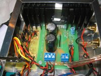
This is the layout of the various caps on the TechDIY board. I skipped all except the large 1,000 uF caps and the little 10 uF cap on the recitifier board, of course.
I skipped C2, C5, C6 and C7. I am very curious about the one on position C7 since that would be an easy add-on right now and the motivation for my original question.
I skipped C2, C5, C6 and C7. I am very curious about the one on position C7 since that would be an easy add-on right now and the motivation for my original question.
An externally hosted image should be here but it was not working when we last tested it.
Hi,
what is the black link in the middle.
That electrolytic standing up from the board, what is it?
Why did you omit all those caps from your installation?
R6 still does not match R2. What is your output offset? have you tried to optimise this?
20k pot into 10k Zin is too high. Have you tried to reduce it to 5k or 2k?
CarlosT said:This is the layout of the various caps on the TechDIY board. I skipped all except the large 1,000 uF caps and the little 10 uF cap on the recitifier board, of course.
I skipped C2, C5, C6 and C7. I am very curious about the one on position C7 since that would be an easy add-on right now and the motivation for my original question.
An externally hosted image should be here but it was not working when we last tested it.
With regard to your statement of lowest off-set being attained making R6 equivalent to the feeedback resistors in parallel is not entirely accurate.
Off-set is a DC component. The statement would only hold true if you did not have an input capacitor and the volume has set to minimum.
From what I suspect is that you got the lowest off-set with the 1K by coincidence and it may be different for another chip.
AndrewT said:...Why did you omit all those caps from your installation?...
Well...for one thing, the layout of the AudioSector GC is very simple and has none of these items. I felt that I could put in a DC input block cap and go from there.
The other issue was packaging...the heatsink interfered with the solder holes for the two little caps (C5 and C6).
Again the result hasn't been bad...
CarlosT said:BTW those were the default values from the TechDIY page. My adaptation is a lot simpler and that's why I'm asking about what to add back in.
This is how mine is laid out.
Why are you going mono?
The idea was to create a cabinet that resembled an old Fender Champ tweed guitar amp that kids could plug in their iPod into and play music. This was an old school look and sound with one driver, no tweeter or crossover, etc. Going stereo would complicate the cabinet build and dimensions and would take away from the "old school" look.
I initially bought the AudioSector LM3875 kit but this is a non-inverting design so supposedly not well suited to combining channels. The inverting design lends itself better to combining channels. If you look at the picture of the "test mule", you can see that I'm cramming everything into a 9" x 5" x 2" Hammond aluminum box so no room for buffer preamp or regulators or any other fancy schmancy stuff. As it is, I got an Avel Lindberg 90VA tranny, an AudioSector rectifier board and a TechDIY amp board and a heat sink all in the little box
I'll post pics soon of the completed project.
fosforo said:Maybe it could be a stupid question but should it be fine to use 2 x 100VA - 18VAC instead of 1 200VA 18-0-18 Vac?
Yes...that should be fine. The larger transformer likely has
better regulation, but nothing to worry about.
Cheers,
Dennis
20+20 vac transformer
= 40 vac * 1.414
= 56.56 vdc / 2 for center tapped psu output
= 28.28 vdc rectified per rail - 0.8v diode drop
= 27.5 vdc per rail
gainclones at peak output in normal configurations are like 50% effecient...
(find the graph in the data)
so 63w * 2 = 126w, plus headroom cuz reality is mean.
so like, a 200VA 20+20vac transformer would be perfect
(i just bought two 400VA toroids to run pairs of 3886 amps =)
Dennis Hui said:
Yes...that should be fine. The larger transformer likely has
better regulation, but nothing to worry about.
Cheers,
Dennis
Yes, sure, but if the total power is calculated by a sum of each power from each seconday then, a transformer with a 18-0-18 200VA isn't the same as two transformer 18VAC - 100 VA?
Obviously we are just cosidering a theoric power calculation
if you parallel the 18+18vac 100va secondary coils on one transformer, you have a single 18vac 100va part. each 18vac half of the secondary coils is actually 50va.
do this to the secondaries of both 100va transformers, put the parallel coils of each transformer in series, creating a center tapped part.
now you have 100va at 18vac + 100va at 18vac
which is basically what 200va 18+18vac toroid is. due to the series/parallel nature of the part you made, id think the combined coils should have about the same inductive and resistive properties as a single secondary coil (half of a center tapped secondary).
so yes, theoretically, mathamatically, its the same. (unless you wanna do all the math for the EM fields from the copper thru the core...)
realistically, its not, but who knows if 2x100va is actually better or worse than 1x200va.
the 100va transformers themselves are prob smaller than the 200va transformers (tho i highly doubt half the volume), so your may be giving yourself more options when making an enclosure for your system. (i remember reading that toroids should be mounted close with their center axis perpendicular to each other, so as not to couple EMI or something.)
- Status
- This old topic is closed. If you want to reopen this topic, contact a moderator using the "Report Post" button.
- Home
- Amplifiers
- Chip Amps
- Which toroidal is ok for the LM3886 and speakers 4 ohm?