I also work on a LM3886 x 2 @ 4ohm project. As i calculated on Overture Design Guide for 4ohm;
@ LM3886TF Pack Maximum Vcc/Vee = 26Vdc and it gives 63W RMS per channel with 1,52CW heatsink for each IC
@ LM3886TA Pack Maximum Vcc/Vee = 30Vdc and it gives 84W RMS per channel with 1,65CW heatsink for each IC
They also can work over that voltages but with really huge heatsinks (lower than 1,5CW) Under that situation,
For TF package 26/1,41 = 2x18v AC
For TA package 30/1,41 = 2x21v AC maximum trafo outputs.
* I dont add the diode losses to the calculations..
Nice days.
25 x 1,41 = ~35v DC without losses. May be you can get 32-33v for each rail. Theorically; i guess it works with 4ohm speakers but i recommend that do not turn volume pot to the end!
- Or you can reduce the voltage gain for; 18K-1K = 19AV
- May be you dont use a preamp, just connect them to the source.
- And a third solution; you regulate DC voltage with two LM338 then you can adjust the output voltage down to 28v.
But for the first two way you must cool the IC very strongly..
Have a nice day.
PS: I am not very experienced member of that forum. There are many "master" members (for ex ink Mouse, AndrewT, NicoRas). I guess you must ask them before apply my solutions.
- Or you can reduce the voltage gain for; 18K-1K = 19AV
- May be you dont use a preamp, just connect them to the source.
- And a third solution; you regulate DC voltage with two LM338 then you can adjust the output voltage down to 28v.
But for the first two way you must cool the IC very strongly..
Have a nice day.
PS: I am not very experienced member of that forum. There are many "master" members (for ex
ink Mouse, AndrewT, NicoRas). I guess you must ask them before apply my solutions.Dxvideo said:25 x 1,41 = ~35v DC without losses. May be you can get 32-33v for each rail. Theorically; i guess it works with 4ohm speakers but i recommend that do not turn volume pot to the end!
- Or you can reduce the voltage gain for; 18K-1K = 19AV
- May be you dont use a preamp, just connect them to the source.
- And a third solution; you regulate DC voltage with two LM338 then you can adjust the output voltage down to 28v.
But for the first two way you must cool the IC very strongly..
Have a nice day.
PS: I am not very experienced member of that forum. There are many "master" members (for ex
Dxvideo, thank you for your compliment. No masters just enthusiasts like yourself.
Dear Personal,
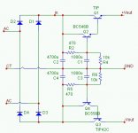
A simple solution is to use a capcitance multiplier as shown. This perform two functions, it will drop the voltage by about 3V and multiply the base capacitance with the combined gain of the transistors.
Because there is not a high volt drop across the series transistor it will not get very hot and moderate heatsink is sufficient.
Attachments
Hi Per,
I just looked up the 3886 datasheet for you.
It says +-28Vdc for 4ohms.
That needs a 20-0, 20-0Vac or 20-0-20Vac transformer. NOT 25Vac.
4ohm and chipamps are not a good mix, if you want cheapness and simplicity.
I use the rule that a good amp will drive half the normal impedance without failure.
So, if you want to drive a reactive 8ohm speaker then the amp should drive 4r0 resistive load.
If 4ohm reactive then the amp should safely and reliably drive 2r0 resistive.
That ability will require an even lower voltage transformer.
I repeat 4ohm and chipamp are not a good mix.
Hi Andrew,
I also had a look see the data sheet and I am in full agreemnt with Andrew on the topic of 4 Ohms.
Since he has the tranformer, what about changing the simple cap multiplier into a regulator replacing the 12 K resistors with 24 V zeners and the 470 Ohm to something like 2.2K.
Although heatsinking would be necessary the tranformer would drop under load when psuhing it and the regulator would not have to work that hard keeping more or less stable temperature rise.
Then again this may sound silly but what about adding two 4 Ohm 10W resistors in series with his speakers, would cost him a lot less and offer more protection. Besides, bass often sounds "nicer" with series resistance.
6 ohm loads
Hi,
I almost finished building my LM3886.
I'm using a 25V transformer also, however my load is 6 ohms.
I entered 37.3V into the overture design guide. 37.3V is what
I'm measuring without a load.
The overture guides gives me a warning error, Required heat sink is too large with TF package.
Could I be missing some other values in the design guide?
I have the Rf=22.1K, Ri/Ci/Rin/Cin=0, Rb=1K
I'm also curious as to if use the Ri/Ci to reduce the output
dc voltage. So anything under 100mV is safe?
Thanks!
Thanks Carlos. I'm using the pcb's from chipamp with the snubber design. So no other values to tweak in.
If I change the impedance from 6 to 8 ohms then the warning is gone.
My only question at this time is if people here omit the Ri/Ci.
I'm waiting for my slab of heat sink today and hopfully will be good to go.
If I change the impedance from 6 to 8 ohms then the warning is gone.
My only question at this time is if people here omit the Ri/Ci.
I'm waiting for my slab of heat sink today and hopfully will be good to go.
Hi Mike,
I suggested starting with four ohm and if all is well go lower, if it is really necessary. Think of it 68W on the speakers is the equivalent to 132W on the devices. Stereo operation is 264 watts of heat. Think of it - 13 x 20 Watt soldering irons worth.
Something confuses me a little, that is their SOA does not really explain how they achieve such high power without destroying the device.
Can anyone shed light on this.
NicoRas you seem very knowleadgeable...can you please address my question here regarding the additional cap across the V+ and V-?
http://www.diyaudio.com/forums/showthread.php?postid=1090688#post1090688
http://www.diyaudio.com/forums/showthread.php?postid=1090688#post1090688
CarlosT said:NicoRas you seem very knowleadgeable...can you please address my question here regarding the additional cap across the V+ and V-?
http://www.diyaudio.com/forums/showthread.php?postid=1090688#post1090688
I am sorry Carlos, of course you can drop a cap across +V and -V as long as it is relatively small. so its charge time is an order or so magnitude lower than the time constant of the input circuit, else you will have both high voltage and current across the series transistor and will surely destroy it.
I use this method on several KRELL clones I built (for non technical audio fanatics) and the resevoir capacitors are 4 x 4700 uF each rail, the base capacitor, in fact I use two is 1000 uF and I have 4700 uF on each rail and each amplifier PCB.
This seems to work out pretty cost effective. There is also no plop on the speakers at switch on and the time to get to rail voltage is roughly 700 mS.
For additional safety I place a reversed diode across the series regulating transistor. The reaon for this is that often when working on and tweaking a new amp you will shurely short the input caps and the output cap will also try and source current in the reverse direction through the series transistors and destoy them.
Of course I do not use TIP41/42, they are the drivers in the KRELL CLONE psu.
Kind regards
Nico
Thanks. I have both 6.8 uF and 2.2 uF film capacitors of appropriate voltage ratings that I could use in this position but I haven't so far. I have built 2 LM3875 IGC mono amps so far without them but just wondered if there was anything to be gained by adding these.
Right now each V+ and V- bank has a 10 uF electrolytic cap at the rectifier board and a 1,000 uF electrolytic cap at the amp board.
I just did not understand the function of a cap across V- and V+.
Right now each V+ and V- bank has a 10 uF electrolytic cap at the rectifier board and a 1,000 uF electrolytic cap at the amp board.
I just did not understand the function of a cap across V- and V+.
CarlosT said:Thanks. I have both 6.8 uF and 2.2 uF film capacitors of appropriate voltage ratings that I could use in this position but I haven't so far. I have built 2 LM3875 IGC mono amps so far without them but just wondered if there was anything to be gained by adding these.
Right now each V+ and V- bank has a 10 uF electrolytic cap at the rectifier board and a 1,000 uF electrolytic cap at the amp board.
I just did not understand the function of a cap across V- and V+.
Hi Carlos, I eventually think I understand what you are saying. For putting a mall cap across +V and -V would lower the impedance at high frquancy and that will be beneficial. There is no real need for a high value capacitor on the amp PCB unless it is some distance away from the power supply board.
I also do not know if theis is the case with the GC but in the olden days many times you found motorboating, a sound like a motorboat over your speakers, which was normally solved with a capacitor 10 - 1000 uF very near the IC'a legs. You would also bypass this cap with a low value cap say 100 nF - 470 nF as large capacitors reveals quite a lot of inductance and low values not improving the high frequency noise on the power line.
Does what I say make sense?
Kind regards
Nico
- Status
- This old topic is closed. If you want to reopen this topic, contact a moderator using the "Report Post" button.
- Home
- Amplifiers
- Chip Amps
- Which toroidal is ok for the LM3886 and speakers 4 ohm?