Hi all..
With AndrewT, Pink Mouse and the other friends assistance i am nearly finish my 2+1 project. But i want to change my subwoofer filter design (which made with Princetons PT2350).
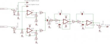
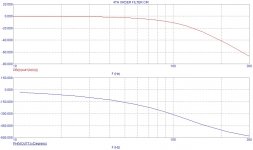
By TI's Filter Pro software i designed a new Butterworth / Sallen Key type 130Hz 4 pole LPF and added a preamp (6dB) stage to it.
I kindly request; please investigate my new design and give some comments on it! May it works perfect or not???
Thanks a lot in advance...
With AndrewT, Pink Mouse and the other friends assistance i am nearly finish my 2+1 project. But i want to change my subwoofer filter design (which made with Princetons PT2350).
By TI's Filter Pro software i designed a new Butterworth / Sallen Key type 130Hz 4 pole LPF and added a preamp (6dB) stage to it.
I kindly request; please investigate my new design and give some comments on it! May it works perfect or not???
Thanks a lot in advance...
Attachments
Hi,
do you realise you can implement the S&K 4pole Butterworth with Equal Value S&K filters that incorporate gain. The resultant gain for the two cascaded 2poles are +1.23db & +6.98db = +8.21db
Close to your required +6db.
The nice thing about EV S&K is that all the resistors are the same value and all the caps are the same value, making matching much easier.
You can also vary the Q very easily by changing the gain without changing any of the frequency components.
This can all be achieved with just two opamps not the four shown.
If the first opamp filter is made MFB instead of S&K then you can bass sum at the input as well.
The DC block at the filter input should not be necessary.
Finally, why the odd filter component values? when 2C or 2R gives Butterworth.
Hi Andrew..
First of all; thank you again for your comment. But i did not do anything but TI's Filter Pro Software's results. So i gave it the cut off frequency, selected type of filter and it gives me that RC values. In fact i could calculate these values by hand but i trusted the software more.
If you say; "its ok it will work perfect" i will apply it before my subwoofer amp.
As the software says. The output signal is 180° different from the input @cutoff frequency (130Hz). Does it make something bad? Or just should i cross the speaker terminals on subwoofer amp?
And a final question; after first stage i summed the channels via 39K resistors then put a DC blocking cap. If i remove the cap. does that situation affect the filters frequency? Because as you can see, after that 39K resistors the RC block starts so the resistors value will be increase! Isnt it?
Best regards.
Hi,
if you have no DC offset being fed into the first opamps then the only offset coming out will be the inherent opamp output offset amounting to just a very few mV.
It is much more important you block or eliminate the DC offset coming from the source.
All these filters assume they have a zero source impedance and an infinite load impedance.
Your DC block and insistence on using the non-inverting summer will completely screw up all the calculations the Ti software is doing for you (and all the effort you will put into trying to measure those differing cap values).
Get rid of it!!!!
Ok then. I will remove the summing stage and DC blocking. And will put the DC blockings to each channels input (but i have already have caps in stereo power stages input!). But at this time does it affect the channel speration? Because i got some problems with that 39K summing resistors in past!
Hi, you're not listening
It is much more important you block or eliminate the DC offset coming from the source.
I somewhat like gain=2 S&K filters. with a gain of 2, the capacitors can be made equal in value. the gain setting resistors are also equal value. the Q is changed by the two other resistors. this is easy to build for arbitrary Q, fixed filters.
gain=1 filters are better suited when the ratio of capacitors makes one cap 2x the size of the other.
gain=1 filters are better suited when the ratio of capacitors makes one cap 2x the size of the other.
To Andrew;
Objection; i am listening but may be i did not understand you clearly! To block DC from source i say "i will put the caps each channels input" means i will put 2µ2 caps to each seperate main input. Is it ok do you think?
And still i have questions about channel seperation problem with channel summing..
For theChris;
As i understand from you; should i fix the capacitor values? and should i fix the gain = 1. Is it?
I feel like silly... I have to go to an English course...
Tanks a lot.
Hi,
it seems to be a mis-understanding
DC at the input to the filter will cause the opamps to go asymetric and they will not perform well that way.
The output offset of the opamps (if they are set up correctly) is negligible (0 to 4mV). But the offset coming from the source could be many volts.
Block the source and the problem goes away.
Fit a good quality 10uF at the output of the source. If you believe you need more then parallel with a 220uF bipolar 16V or 25V (Rane recommend Panasonic)
it seems to be a mis-understanding
the "but" gives the impression that you think that blocking at the input to the power amp cures the problem.(but i have already have caps in stereo power stages input!).
DC at the input to the filter will cause the opamps to go asymetric and they will not perform well that way.
The output offset of the opamps (if they are set up correctly) is negligible (0 to 4mV). But the offset coming from the source could be many volts.
Block the source and the problem goes away.
Fit a good quality 10uF at the output of the source. If you believe you need more then parallel with a 220uF bipolar 16V or 25V (Rane recommend Panasonic)
not if you use the virtual earth of an inverting input stage, which is why I keep pointing you to MFB.And still i have questions about channel seperation problem with channel summing
Dxvideo said:For theChris;
As i understand from you; should i fix the capacitor values? and should i fix the gain = 1. Is it?
I feel like silly... I have to go to an English course...
Tanks a lot. [/B]
there are three common s&k filters. if gain = 1 (easy to do) then the Q of the system is controlled by the ratio of capacitors if the resistors are equal value. capacitors are not always avaiable in the correct ratio. if gain=2 (2 equal value resistors for opamp gain, so fairly easy), then the Q is set by the ratio of the resistors and the capacitors are equal value. The final case is where the caps and resistors are equal values, in this case the Q is set by the stage gain.
because of the difficulty in finding good ratios of caps (in a general case), i like the gain=2 circuit.
I'll try to post a picture of a normalized circuit later
Adding a sub-woofer to your system is not quite a matter of choosing an abritary frequency. The sub woofer can interfere with your normal speaker response.
Normally I would roll-in the sub-woofer at the point where your normal speakers are starting to fail in response.
There is quite servere phase change over the range of the sub-woofer and rolling it in at the wrong point could cause a hole in bass response which may sound a lot worse than it did before.
My suggestion is first find the spot that your normal speakers bass is starting to lack then choose that frequency for your sub-woofer roll-in point.
You also need a very sharp slope so that any higher frequencies does not interfere with your normal speaker response.
I have designed a sub-woofer circuit for my own use and it complements my normal speakers. It works well and I am a music lover, not necessarily into sound effects.
Because you are working with such low frequencies and no gain, you can use almost any op-amp in your box.
Attachments

If you would like, e-mail me and I will send you a set of gerber plots for the PCB the complete circuit diagram and parts list.
Although a low-pass filter and sub-woofer is the norm, I prefer a Linkwitz Railey correction which does make a significant difference and you normally won't need a sub-woofer unless you want to demolish the house..
Although a low-pass filter and sub-woofer is the norm, I prefer a Linkwitz Railey correction which does make a significant difference and you normally won't need a sub-woofer unless you want to demolish the house..
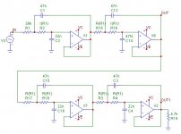
Attached is the Sub-Woofer Filter that may be useful to you. Changing the values of the resistors to half that shown, such as 18K will double the frequency and be close to your required 130Hz.
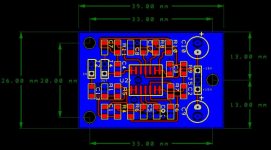
The attached Gerber files will allow you to have a PCB made. I used Surface Mount components and the all the components should cost you no more than 3 - 4 Euro.
Should you have any queries feel free.
Kindest Regards
Nico
The attached Gerber files will allow you to have a PCB made. I used Surface Mount components and the all the components should cost you no more than 3 - 4 Euro.
Should you have any queries feel free.
Kindest Regards
Nico
Attachments
Thanks a lot Nico...
They all will be very useful for me.. The circuit looks like non inverted. But for best channel seperation Andrew recommend inverted stages. At this time i have a channel summing problem. Because in past, i made two 39K summing circuit for my low pass filters and i had channel whispering problem a lot. What can you say about that?
Best regards.
- Status
- This old topic is closed. If you want to reopen this topic, contact a moderator using the "Report Post" button.
- Home
- Amplifiers
- Chip Amps
- Subwoofer filter design comments!