I'm currently comparing various Panasonic caps for an IGC kit and wondered what are the more important specs. The kit calls for 1,000uf 63V caps and the kit comes with Panasonic NHGs. However, Panasonic makes other caps in that range that have higher endurance, higher ripple and lower impedance. What is important?
Panasonic NHG 1,000uf 63v
Cost $1.78
Size 16mm x 25mm
Ripple Current 930ma
Impedance .1
Endurance 2,000 hours
Panasonic FC 1,000uf 63v
Cost $3.33
Size 16mm x 35.5mm
Ripple Current 2,770
Impedance .036
Endurance 5,000 hours
Panasonic FM 1,000uf 50v (no 63v available)
Cost $1.30
Size 16mm x 25mm
Ripple Current 3,320ma
Impedance .016
Endurance 7,000 hours
Is it strange that the "better" spec'd FM caps are cheaper? Am I totally missing the picture here?
You did not quote ESR for any of those caps
The panasonics looks fine for a GC with 28V supply into 4 ohm.
The panasonics looks fine for a GC with 28V supply into 4 ohm.
From what I hear, it is more the "sound" of the component itself than the specs that are important.
Many have said that the Panasonic FC is their cap of choice in GCs. The Rubicon ZL is also a good choice for inverted GCs (and the specs are excellent!)
Sometime ago, people were raving about the Black Gate caps. I don't know what their specs are, but I believe that they have a different sort of construction to the conventional electros. It seems as though BG caps have fallen from favour in the GC circles in the last couple of years...
As for specs, what we should probably look for are high ripple rate and low ESR. It makes for a longer life cap too, if I guess correctly.
I believe that the impedance rating is related to the oft-quoted ESR...lower is better? Anyway...I'm gonna give the FMs a try.
Yes lower is MUCH better, the lower, the faster the cap can "slew".
Forget about the capacitor as a capacitor for a second and only think of it being a resistor, now using ohm's law see how significant the impendance is on current delivery and ripple absorption.
I'm afraid what is good for a class A PSU is not good for a class AB, and probably vice versa.
I need to quote an article on solidstate PSUs from TNT audio
One source of noise is a "power vacuum" where more power is required than can be instantly provided.
Forget about the capacitor as a capacitor for a second and only think of it being a resistor, now using ohm's law see how significant the impendance is on current delivery and ripple absorption.
I'm afraid what is good for a class A PSU is not good for a class AB, and probably vice versa.
I need to quote an article on solidstate PSUs from TNT audio
You see, filter capacitors should be just that, FILTER capacitors, their energy storage function being of secondary importance. In many commercial units, these roles are present but reversed - larger value capacitors are used not only for filtering, which they cannot help but do, but also to act as energy reservoirs.
Of course, they always act that way, but the point is that they tend to be increased in capacity to cover for inadequate power transformer size and/or performance.
In such cases, you are not very likely to find high quality capacitors inside, but rather those of commercial quality. There are two basic reasons for this. The first is that they are cheap, and can be made to look good on ad photos and in ad sales blurb.
The second is that by connecting two capacitors in parallel, one not only doubles their energy reserves, but also cuts their output impedance in half. This is of course quite true, and in practice works every time without fail, but in essence is much less than we are led to believe.
So halved output impedance may still be above the values obtainable by using a single pair of high quality capacitors. Also, this view completely disregards capacitor charge and discharge speeds - good quality caps are expensive precisely because they are, among other things, very fast.
By way of example, a typical commercial value capacitor, rated at 10,000uF/63V and costing some Euro 8-9, will have a speed of 30-40V/uS at best. An equivalent Elna for Audio series black, costing some Euro 15-25, will have a speed in the range of 80-90V/uS, i.e. at the very worst, double the speed of the best case in commercial cap land. A Siemens Sikorel cap, costing some Euro 20-30, will slew at over 100V/uS - but at a price.
One source of noise is a "power vacuum" where more power is required than can be instantly provided.
ash_dac said:
1000uf !
Isn't that a bit low ?
Why?
Above about 1500uF at the chip of a GC with a normal unregulated or un-snubbered power supply is generally Not A Good Thing.
falcott said:
Why?
Above about 1500uF at the chip of a GC with a normal unregulated or un-snubbered power supply is generally Not A Good Thing.
Ok so the main large caps are near the diode bridge ?
ash_dac said:
Ok so the main large caps are near the diode bridge ?
The GC doesn't like a lot of capacitance, so 1000uF - 1500uF close to the chips is about as much as you can give it. Some GCs don't even have any caps in the PSU... 😱
The caps on the AudioSector rectifer boards are puny compared to the decoupling caps on the amp board.
Geez people.
Fact: 1500µF is still NOT ENOUGH! You will need at at least 4700µF over + and -. Two 4700µF caps, one over + and GND, and one over GND and - will be even better for a psu.
You may want even more!
Fact: 1500µF is still NOT ENOUGH! You will need at at least 4700µF over + and -. Two 4700µF caps, one over + and GND, and one over GND and - will be even better for a psu.
You may want even more!
I'll second the cap comment about 1500 being a little low. I was less than pleased with the bass response at lower cap values. I personally have about 10K per rail in the PSU and bypass that on the board. (Oh, and I like the Linkwitz LM3886 circuit better than the gainclone circuit, but that is a different story for a different day. . . )
EDIT: I just thought to add that I have tried using 1500 uf caps on the boards power input, bypassed next to the chip, with 10K caps on the PSU rails. Though this is a little overkill, it seems to sound better full range to me.
EDIT: I just thought to add that I have tried using 1500 uf caps on the boards power input, bypassed next to the chip, with 10K caps on the PSU rails. Though this is a little overkill, it seems to sound better full range to me.
The last pcb's I used for the lm3886 had four 4700uf filter caps... two should be the bare minimum.
let's see it...
falcott said:
Some GCs don't even have any caps in the PSU... 😱
let's see it...
elementx said:
let's see it...
Ok, I can't find pics right on the spur of the moment, but this quote is about the original Gaincard that started all this (quoted from Mick Feuerbacher's site)
The PSU (Power Humpty)
This information was collected from other sources in the internet. The Power Humpty contains a high quality non-toroidal 170 VA transformer. Secondaries are 23.5V, 3.6 A. There are only four diodes, used for the positive and negative rails. The diodes are FE5D 9808 (General Semiconductors). There are no capacitors in the Power Humpty. The ground connections of the positive and negative rail are separately led to the amp boards.
Peter Daniel's LM3875 kit, and BrianGT's earlier kit, have only 4.7uF per rail in the PSU.
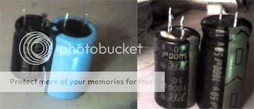
I'm trying the Panasonic FM in the "puny" 50 v 1,000uF size 'cause that's as big as they make them and that's what Jack shows in his diagram.
Thanks again, JacknJoisey for updating and clarifying the values.
An externally hosted image should be here but it was not working when we last tested it.
Thanks again, JacknJoisey for updating and clarifying the values.
Re: 4780 kit
Lets' say that there's a simple pair of little caps on the rectifying board like in Pete's AudioSector kit. Is there any interaction that one needs to worry about with the bigger caps on the amplifier board? I noticed that Peter's LM3875 amp board does not have any parallel little caps...maybe that function's already taken care by the little caps on his rectifying board?
Bicycleguy said:Pete's 4780 kit has 10uf on the psu, but states you can go up to 100uf.
Lets' say that there's a simple pair of little caps on the rectifying board like in Pete's AudioSector kit. Is there any interaction that one needs to worry about with the bigger caps on the amplifier board? I noticed that Peter's LM3875 amp board does not have any parallel little caps...maybe that function's already taken care by the little caps on his rectifying board?
Hi,
post 18 rev Dec2, 2006.
Is the input impedance of the non-inverting chipamp=1k0?
Is the F-3db frequency=1/[2Pi *4.7uF*1k0]=34Hz?
and phase error upto 340Hz?
The statement at the top of the schematic seems suspicious:- setting R6=R2//R3 But R3 is DC blocked by C1. I think R6=R2+-variation to trim output offset.
The feedback tapping AFTER the half Thiel network seems odd.
Should it be BEFORE the Thiel? i.e. at node 3?
How far away are C5 & C6 from the supply pins1&4?
- Status
- Not open for further replies.
- Home
- Amplifiers
- Chip Amps
- Capacitor Choices...What's Important?