Hi
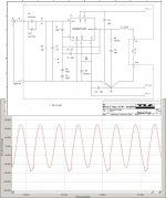
I have a problem with the gainclone I made, please take a look at the attached picture.
The picture output signal is a 200Hz (but also happens to 500hz of 1Khz) and about 13V RMS, this is actually where the clipping starts but only for the lower half of the signal.
My PSU is 31.6v and the testing load is a resistive 8 ohm (made by parallel resistors).
The output is about 21 watts (from P=V*V/R) and is very low since the amplifier should have an output of about 40W before clipping.
Both psu rails are ok with 31v DC and very low ripple since I have 10000uf in each rail.
Can someone please suggest what might be wrong, it doesn’t seem to be the (internal) spike protection circuit.
Thank you
Alex
Attachments
Alex--
One of us is reading your graph wrong...
To me, it looks like Vp-p is about 50 volts (+/- 25V). This is about 17.6 VRMS, which translates into about 39W into 8R. Judging by the datasheets, you should be below the clipping point, which is about VCC-2.7V at this supply voltage.
The fact that the waveform is only distorted every other cycle suggests to me that you're probably at the SPiKe limit. Try blowing a fan at your heatsink to see if it goes away at this level.
Good luck--
Greg
gmikol said:Alex--
One of us is reading your graph wrong...
To me, it looks like Vp-p is about 50 volts (+/- 25V). This is about 17.6 VRMS, which translates into about 39W into 8R. Judging by the datasheets, you should be below the clipping point, which is about VCC-2.7V at this supply voltage.
The fact that the waveform is only distorted every other cycle suggests to me that you're probably at the SPiKe limit. Try blowing a fan at your heatsink to see if it goes away at this level.
Good luck--
Greg
Thank you for your reply.
The graph in the picture is not scaled (it's from my audio card and a measuring circuit as buffer and both are below the clipping region).
The signal is 13v rms (over the 8 ohm load) measured with a multimeter since its 200hz and the measurement is accurate.
The chip is mounted directly to a big heat sink+blower (with paste between the chip and heatsink) and the temperature measured at the chip (not the heatsink) is about 30 celsius (with a digital thermometer)
I can't explain what is wrong an the spike protection in the datasheet for LM3186 shows a different graph for when the spice protection is working.
On the other hand it seems to be a protection because if i let the chip heat this clipping occures a little lower but the output watts but the output is very low at about 20W.
The temperature measurement can't be wrong because i can even feel it with my hand.
Thank you
Alex
I don't find it very unlikely
that your amplifier start showing clipping at +-25V
if your rails are at +-31.6 V, when amplifier is at idle.
But what is the supply voltage when you get this clipping?
Some supply can be several Volts lower under such high power
as near to 40Watt RMS.
4-5 volts is not uncommon for some amplifiers.
What is the VA rating of your trafo?
Very big trafo will not drop voltage as much
as normal size transformer.
Class A amps, have same supply voltage all the time.
But here we are talking about a lower biased Class AB.
Why is unsymmetrical clipping showing?
Yes, because LM3886 just like LM3875 is not a symmetrical design.
lineup
Attachment:
Shows that the good LM3875 is not at all symmetrical
( LM3886 is almost identical, basically )
Attachments
lineup said:I don't find it very unlikely
that your amplifier start showing clipping at +-25V
if your rails are at +-31.6 V, when amplifier is at idle.
But what is the supply voltage when you get this clipping?
Some supply can be several Volts lower under such high power
as near to 40Watt RMS.
4-5 volts is not uncommon for some amplifiers.
What is the VA rating of your trafo?
Very big trafo will not drop voltage as much
as normal size transformer.
Class A amps, have same supply voltage all the time.
But here we are talking about a lower biased Class AB.
Why is unsymmetrical clipping showing?
Yes, because LM3886 just like LM3875 is not a symmetrical design.
lineup
Attachment:
Shows that the good LM3875 is not at all symmetrical
( LM3886 is almost identical, basically )
Hi
The graph i posted is not scaled, the true signal amplitude is 13vrms (+-18v peak or 36 peak to peak) at a resistor of 8 ohm which is about 20W rms.
The psu is from 2 separate transformers 300VA/ 24v AC each and are center tapped and rectified with one bridge and the center tap for ground.
Both plus and minus psu rails have the same voltage because both transformers were bought together and have the exact same secondary windings
The +- 31.6v DC (measured with full load and an ac ripple of 30mv) is very stable since i have only one amplifier connected to the transformer and 10000uf in each psu rail.
Alex
I'll try the mute resistor, thank you.
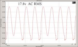
In the meantime please chech the attachement of this post which is for 17.8v RMS output which is about 40 Watts.
As you can see the positive slope looks fine and the negative slope just gets worse.
Can it be a damaged IC? i just bought it and it is the first time i use it in a circuit, it also sounds fine untill the clipping occurs.
Alex
Doesn't it look like some form of instability ?
To me it doesn't look like normal clipping.
Check your supply lines with a scope. Note that the 200Hz signal has a problem with each alternate cycle. That is 100Hz and that is the ripple frequency . So is one half of your rectification having a problem ? You must check with a scope to see what's happening.
EDIT: OK your second picture shows more than every alternate cycle. Check your supplies in any case . Did you use the 100pF cap on the NFB resistor ?
I would make a check that you have all components
put together correctly.
Especially look for electrolytic caps,
are put into circuit with correct polarity + -
And that all capacitors have got good voltage rating.
There can be is some connection, some component, that is not put the right place
or you have wrong polarity.
Or maybe one end has got bad solder and not in contact.
Also putting in a component, resistor with wrong value.
It is not too difficult to mix up, and put an 10k instead of 1k
because they look almost the same!
We can have 99 components put right
but only 1 not right,
and your circuit wont work good!
If mains is 50 Hz, Try run your test at 175 Hz... or for example 225 Hz.
Because 200 Hz is a second harmonic of 100 Hz and
full bridge rectified voltage is pulsed with 100 Hz.
50 Hz full wave recitifier
will work at 100 Hz
and produce: 200, 300, 400 harmonics
That is, if you do not use 60 Hz mains,
in which case your full wave DC will have pulses at 120 Hz,
and harmonics are 240, 360, 480.
lineup
Thank you all for your help.
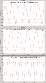
I had a feedback capacitor of 1n (in parallel with the negative feedback resistor) insted of 100p and this caused all the problem but i still can't understand why since this cap only lowers the gain for HF.
Please take a look at the attached image (not scalled but all there have the same scale and can be compared).
The first is of a 18v rms with 1n NFB capacitor, the second is with the exact same output but with 100p cap (or none which had the same result) and there is no clipping at all.
Finally the last one is the maximum output i could get without distortion and it was 19.5v rms which is about 47 watts , THD was about 0.003%.
Thank you once again
Alex
Attachments
")
Great!
Good you found the solution
Now your data are okay
and your test results shows very nice images!
You should know and you probably do,
that for LM3886 47 Watt RMS is a high and good figure!
And good with LM3886, if compared to LM3875,
is that it likes and can take 4 Ohm speakers better,
at least when the output currents peaks get in higher range
I am happy for you
But you are probably >=10 times more happy
Now you got yourself one good amplifier there .....
lineup
The cap reduced the gain at certain frequencies to below 10. These chips require a gain of 10 or greater to be stable. That, combined with the phase shift from the (too large) capacitor is what caused the instability that lead to the distortion.I had a feedback capacitor of 1n (in parallel with the negative feedback resistor) insted of 100p and this caused all the problem but i still can't understand why since this cap only lowers the gain for HF.
Please take a look at the attached image (not scalled but all there have the same scale and can be compared).

macboy said:
The cap reduced the gain at certain frequencies to below 10. These chips require a gain of 10 or greater to be stable. That, combined with the phase shift from the (too large) capacitor is what caused the instability that lead to the distortion.
I guess that this explains the distortion in the waveform.
Thank you all
Alex
- Status
- This old topic is closed. If you want to reopen this topic, contact a moderator using the "Report Post" button.
- Home
- Amplifiers
- Chip Amps
- LM3886 clipping at 13v rms