Hi all,
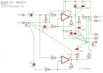
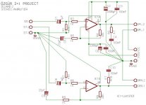
I'm working on a DIY 2+1 project (in fact for over one year!). I use one LM1876 NI in parallel to drive a 4ohm woofer and one LM1876 NI stereo to drive two 8ohm satellites. I made a good PCB design with your precious assistance. I purchased all the components. And finally i'm working on last details.
For input coupling i use 1µF, 47K (for input resistance) and 1K serial. As you recomended about coupling capacitors i bought two type of cap. that
- 1µF %10 400v Philips MKC
- 0,68µF %5 250v ERO MKP
They're very big caps (12x30x23mm) and i cannot find any bigger capacity MKC or MKP caps. or lover voltage of them. So the question;
-Which capacitor should i use for coupling?
And another question;
-For feedback capacitor as you can see i use 22µF electrolythic. Should i use a MKC or MKP for it? But in this case its very very hard to find it!
Thanks a lot for your helps.
With my best regards,
Özgür
Attachments
Make sure the 10uf electro is non-polarised, if you feel the need, you can bypass it with a 0.1u, but for a sub, I wouldn't worry. As for the input caps, you can always mount them off the board. I have some axial 4.7uf I use and I have used them to replace the input wiring between the input socket and the board.
Hi,
somebody using a chip amp that understands the difference between signal ground and power ground. Yahoo!
What are pin 5 & 10?
Leach and a few others connect the signal ground and power ground on board using a 10r to provide a SHORT route between them rather than the LONG route via the connecting cables back to audio ground. Using 10r avoids the hum loop.
The input high pass filter at 1uF and 47k for a sub is a bit high. I would suggest aiming for 80 to 100mS instead of 47mS.
Do you have DC blocking at the source output?
Then you need to calculate the effect of the three impedances. source cap, into parallel combination of receiver series cap and Zin to ground.
R5*C5 & R9*C9 are far too low @ 22mS.
they should be at least half an octave lower than the input high pass filter.
47mS needs at least 66mS at the NFB and 90mS needs at least 130mS.
When selecting the values for the main amplifiers you can go a decade (or more) higher than this if it allows you to go exclusively for film caps.
You can choose to bypass all the electros with metallised plastic film caps across the electro pins. There is a view that the inductance of the wiring between electro and film cap leads to (severe) ringing that is bad for sound. But equally the view that keeping the ratio between electro and film >16:1 and using pin bypassing avoids the same problem.
Do both and measure/listen. Then tell us the results.
No low pass RF filter?
Hi,
just noticed C3 and C7 using long routes to the PCB power ground.
These should be VERY close to the chip amp power pins and connected to each other by the VERY shortest route. Then the 0v trace taken to PCB power ground. SMD under the chipamp pins would be ideal.
I would recommend you take the speaker return direct to the audio ground and not to the PCB connection SPW-1.
Hi
For Pink,
Do you mean 1µF? Because there is no 10µ in circuit. And sure that its a non polarised cap. I already designed the PCB and theyre on the PCB. As i understand you use electrolythic capacitor for input (u say 4.7µ axial) is it? Thanks a lot.
For Andrew,
-Thank you and youre right; finally i understand the difference between power gnd and signal gnd (after very bad experiences!).
-The pins 5 and 10 is signal ground as Pink said then i connected them to star gnd point on the PCB.
- Yes i plan to connect signal GND to power gnd via a 10ohm resistor as you say.
-I have an MS excel macro that written by National's team. And it says if i use 1µF and 47K input filter the lower (-3dB) cut off will be 7Hz with 20K-1K-22µF feedback... But i cannot understand what you writen; 80 to 100mS instead of 47mS?? You mean mF?? Sorry.
-I havent got any coupling cap. before power amp. I use a premp block plus a HPF for sat. and LPF for sub. amp but they have no DC blocking caps on output stage.
Will be continiue very soon. I have a meeting and will be back in one hour.
Hi,
what do you mean "meeting" has priority over DIYaudio!. You're sacked.
The input filters can be described by their RC time constant rather than frequency. The DC blocking filter is shown as 1uF and 47k. the RC time constant is 47000ohms*1uF*10^-6 = 0.047Seconds = 47mS.
This single pole filter has F-3db @ 3.4Hz.
For a wideband amplifier driving a wideband speaker I think this filter frequency blocks too much of the bass signal since it's influence goes all the way up to about ten times the turn over frequency.
I have found that bass keeps improving (with the same speakers) if the amplifier uses F-3db between 1Hz and 2Hz. This can be achieved as described earlier. (this is equivalent to -1db @ 2Hz to 4Hz that many commercial amp and pre-amps use).
The amplifier uses three turnover frequencies and each interact with the others.
To ensure stability the highest filter frequency should be the DC blocking input filter.
The next should be the NFB DC blocking filter. This should be set at least half an octave below the input filter.
Finally the last is controlled by the PSU. This should be set a further half octave below the NFB filter.
The PSU RC is speaker impedance*smoothing capacitance
If you use 4ohm speaker you should use at least 0.094S/4ohm = +-24mF of smoothing in the power supply to the pair of chipamps. You could split this into +-12mF to EACH chipamp since each is effectively feeding an 8ohm impedance.
Using 4ohm speakers demands double the smoothing capaitance. If you want good bass then don't skimp here.
Summarising.
If you keep the input filter at 47mS then NFB > 1.4*47=66mS and the PSU >1.4*66=94mS
But back to my recommendation
Input 90mS.
NFB 130mS.
PSU 180mS.
BTW.
are there any recommendations for matching the gain setting resistors when you parallel the chip amps?
Is +-1% good enough? worst combination of errors will result in a <4% difference in gain between the two chipamps.
Your DMM can manage a lot better for matching (absolute accuracy is not important).
0.1% matching can reduce the gain error to <0.4%.
I'm sorry Andrew. Of course is nothing important than DIY Audio. Its a life style and no more priority level than that. So youre right. But it was a planned meeting so i cannot delay and cannot make over 15 persons wait.
First of all, its too complex for me. As my knowledge (before now) 7Hz was a good cut off frequency for an amplifier. But you say NO!
My subbox has a 32Hz (-3dB) F3 and i supposed its enough to have a 20Hz cut off amplifier. So i collapsed!
As i said its too complex for me: three turnover frequencies, RC time constants etc...
Please inform me as simple as possible and forgive me for my poor linear knowledge!
These are the questions;
For parallel amplifier (to drive 4ohm woofer);
* Should i replace the input capacitor with a bigger one? (4.7µF or more?)
* Or should i replace the input load resistor (47K)?
* Or (2) should i remove the coupling cap totally? I think that way because i have a feedback cap already. As my poor audio knowledge it stops the DC amplifying. Is it?
For seperated amplifier (to drive 8ohm sats);
* Does 1µFs ok for 130Hz roll off? Because my HPF cuts -3dB at 130Hz already.. Or you recommend another way?
And for final;
* You say my %1 toleranced gain resistors make %4 gain difference between two amplifiers. So it makes a power reducing is it? Should i use %0.1 tolerance resistor set?
FOR THE CONCLUSION: I AM VERY CONFUSED!
Thank you very much.
Hi,
Sub-Bass chipamps:
for the input filter change C1 & C9 to either 1u8F or 2u2F or parallel two 1u0F//1u0F
For the NFB filter change C5 and C8 to 120uF and change R5 & R6 to 1k1 or 1k2 and R4 & R8 to 22k or 24k
For the PSU fit +-12mF to each chipamp fed from their own rectifiers.
Main chipamps:
set filter @ <30Hz to be 2octaves or more below the speaker turnover. 30Hz needs >=5mS, >=7mS & >=10mS.
input 0u33F & 47k (15mS)
NFB 22uF & 1k0 (22mS)
PSU >=+-4mF per chipamp. (32mS)
This leaves the bass amp -1db @ 3 or 4Hz.
Main amp is -1db @ 21Hz.
the 22uF could be 50V bipolar.
the 120uF could be 25V but if not bipolar or not 50V then protect it with a pair of inverse parallel zeners about 3v9.
Remember, I said find corroboration for the gain matching. I made an observation, I do not know how critical the match is for balance across the two chipamps with that 0r1 on the outputs.
Thanks a lot. I'll apply your recommendations on my project. But i have questions about parallel amp.s gain matching..
If i use %1 tolerance resistors and measure the resistors actual values then fix the same value resistors on same amplifier may i reduce the unmatching gain problem with them?
If i use %1 tolerance resistors and measure the resistors actual values then fix the same value resistors on same amplifier may i reduce the unmatching gain problem with them?
Hi,
you only have one pair of paralleled chip amps.
So, you only need to match one pair of lower leg resistors and one pair of upper leg resistors.
Again I say "absolute accuracy" is NOT required. Just use the same readings from your DMM set to resistance with as near full scale as your meter allows. eg. 2000r setting will measure to 1999r so two resistors measuring 1998 and 1997 are close enough (0.05%).
If you are slightly over scale, then use the 20k setting and then you measure 2.01 and 2.01 (max error is 0.01 and this is 0.5%).
Do you see the advantage of trying to get near full scale when matching?
IF you need to match at all.
Has anyone else using paralleled chipamps referred to matching paralleled gains?
Ok its very clear now! That misunderstanding cause from my poor English and i'm sorry again. I have a 4000 count DMM so i can measure up to 3,999ohm with 1 ohm uncertainity and 39,990ohm with 10ohm uncertainity. So i can find 19,990 or 20,010 ohm then it means 5 %00 acuuracy.. I hope i'm on right way and not still in missunderstanding position... Thanks a lot.
And for conclusion,
For woofer amplifier;
Input DC blocking cap will be 2 x 1µF (in parallel) MKP
NFB resistors will be 22K and 1,1K %1 tolerance (but mached with DMM measuring method)
NFB capacitor will be at least 120µF and bipolar.
And i can get 3-4Hz roll off
For satellite amplifier;
Input cap will be 0,33µF MKP and input load resistor stays 47K
NFB resistors stay at 20K - 1K
NFB cap stays at 22µF
Then amp gets 21Hz roll off.
I dont use PSU caps (but 2200µF's on amp boards) because i use SMPs (2 x 24v 4.5A from MeanWell) and will connect the first PSU's +24v point to seconds GND.
Thats all?
 or
or 
My silence is because SMPS is outside my expertise.Dxvideo said:I dont use PSU caps (but 2200µF's on amp boards) because i use SMPs (2 x 24v 4.5A from MeanWell) and will connect the first PSU's +24v point to seconds GND.
I cannot offer any advice with regard to suitability/compatability.
I'm surprised! I made all my design on that SMPSs and in fact i have no additonal precaution for any additional noise...
With all my respect; i want to ask "how can they use SMPSs on radio circiuts (f.ex:sat.receivers) or how can high-end PC sound cards live on a PC with 108dB SNR???"
Sure i can use my oldie 2x18v 250VA (but EI) transformer for this prject but i want to know why??
Thanks a lot gents...
My best regards.
Hi,
I have never heard a high end PC audio card.
But I have heard many run of the mill audio cards and I just leave the sound on my PC switched off (permanently).
It is not worth the effort trying to get good sound out of my PC.
My audio equipment plays good audio.
My PC is good at number crunching and any smps in there is going to prevent that easy path for good audio to ever escape.
- Status
- This old topic is closed. If you want to reopen this topic, contact a moderator using the "Report Post" button.
- Home
- Amplifiers
- Chip Amps
- Coupling cap.question..