Well, I have built myself a GC based on carlosfm's non inverted schematic and "snubbered" regulated PSU along with a soft-start from Rod Elliot.
I've got a single channel hooked up, it all turns on an off just fine. The relay click happens very shortly after I flick the power switch. Probably more than 100ms, but definately less than 1s... lets say 500ms") .
.
I checked the offset, with no input signal, using a 10R 7W resistor, before hooking up a test speaker, and I got 92mv (a little high but probably nothing to worry too much about at this point?).
So next I plugged in the speaker, still without an input signal. Silent turn on, strange high pitch click on turn off. Speaker didn't seem to be blown, but it made that strange click on turn off every time.
The moment of truth. My current amp, a Cambridge Audio A5, has a "PRE OUT", which appears to mean it's the output of the preamp. Seems obvious enough, so I assume that's exactly what it is and I was hoping to use it purely as a pre-amp for now. I plugged one channel in to the pre-out and then plugged the other end in to the GC input. Sat hesitating for about a minute, and, while playing music, turned on the beast with the volume control WAY down. It was LOUD, very loud, and as far as I could tell the volume control was doing nothing at all to quieten it. It was, however playing music. I turned it off, checked everything... and tried again, it was still loud. I think the fuse blew when I turned it off that time.
What worries me is that it was so damn loud and the volume control was doing sweet FA. I measured the pre-amp output and it only seemed to be ~300mv, BUT this figure didn't seem to be changing when I twiddled the volume control either I suppose this is something wrong with my current amp. I'll worry about that later I guess.
The fuse I used is a 3.15A quick blow, and I have a 500VA toroidal transformer (originally was going for 300VA, but the 500VA was cheaper at the time!!) which might not be enough I guess? I have a 5A slow blow, but I am a little worried about turning it on with that though!?
Oh, also, as it's not in a case I haven't connected anything to the safety earth pin yet ( yes yes, call me an idiot but what am I supposed to connect it to at this point? ). Might this also have something to do with it, or not?
For what it's worth I didn't seem to see or smell any smoke, it just wouldn't turn on so I checked the fuse... and it seems the waxy stuff inside melted. Nice and green in there now Hopefully this is a good sign!
I've got a single channel hooked up, it all turns on an off just fine. The relay click happens very shortly after I flick the power switch. Probably more than 100ms, but definately less than 1s... lets say 500ms
. I checked the offset, with no input signal, using a 10R 7W resistor, before hooking up a test speaker, and I got 92mv (a little high but probably nothing to worry too much about at this point?).
So next I plugged in the speaker, still without an input signal. Silent turn on, strange high pitch click on turn off. Speaker didn't seem to be blown, but it made that strange click on turn off every time.
The moment of truth. My current amp, a Cambridge Audio A5, has a "PRE OUT", which appears to mean it's the output of the preamp. Seems obvious enough, so I assume that's exactly what it is and I was hoping to use it purely as a pre-amp for now. I plugged one channel in to the pre-out and then plugged the other end in to the GC input. Sat hesitating for about a minute, and, while playing music, turned on the beast with the volume control WAY down. It was LOUD, very loud, and as far as I could tell the volume control was doing nothing at all to quieten it. It was, however playing music. I turned it off, checked everything... and tried again, it was still loud. I think the fuse blew when I turned it off that time.
What worries me is that it was so damn loud and the volume control was doing sweet FA. I measured the pre-amp output and it only seemed to be ~300mv, BUT this figure didn't seem to be changing when I twiddled the volume control either
I suppose this is something wrong with my current amp. I'll worry about that later I guess.The fuse I used is a 3.15A quick blow, and I have a 500VA toroidal transformer (originally was going for 300VA, but the 500VA was cheaper at the time!!) which might not be enough I guess? I have a 5A slow blow, but I am a little worried about turning it on with that though!?
Oh, also, as it's not in a case I haven't connected anything to the safety earth pin yet ( yes yes, call me an idiot but what am I supposed to connect it to at this point?
). Might this also have something to do with it, or not?For what it's worth I didn't seem to see or smell any smoke, it just wouldn't turn on so I checked the fuse... and it seems the waxy stuff inside melted. Nice and green in there now
Hopefully this is a good sign!Hi,
how often do we need to tell everyone.
Use a mains light bulb wired in series with the live mains feed to test the unit from the mains, to avoid catastrophic blow ups.
It is cheap and potentially saves a fortune in damaged components if something has been mis-wired, transformers and caps particularly.
Output offset is measured with the output open circuit and the input short circuit. Do it again correctly and if it is still near 100mV then fix it first.
Come back with the correct offset reading while it is still connected through that light bulb.
AH! I misread / misunderstood something somewhere then. I thought the output was just supposed to have a "load" to test the offset.
I guess just a wire from input +ve to input -ve on my board is OK? That would be what shorted means right?
By the way, I know about the light bulb thing. I just dont have a spare to do it with. My own risk and all that, yes, I know!
PS thanks for your really quick reply!!
EDIT: still ~90mv
I guess just a wire from input +ve to input -ve on my board is OK? That would be what shorted means right?
By the way, I know about the light bulb thing. I just dont have a spare to do it with. My own risk and all that, yes, I know!
PS thanks for your really quick reply!!
EDIT: still ~90mv
Hi,
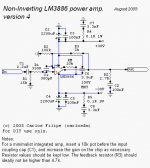
first glance shows that Carlos is using mixed AC & DC coupling. That is not good for output offset and offset stability.
I recommend fully AC coupled or fully DC coupled, not mixed.
DC coupled means DC input at the non-inverting input pin AND DC feedback at the inverting input pin.
AC coupled means DC blocking capacitor in the input line to the non-inverting input pin (as shown in the schematic) AND DC blocking capacitor in the lower leg of the NFB loop.
Mixed AC & DC coupling means one of the DC blocking caps is omitted.
By DC coupling you be refering to the 3.3uF cap between the power rails, I assume? Or the 300nF between input pins? Or even both of these?
Regardless, I do seem to recall carlos saying his DC offset with that circuit was < 50mv. Probably partly to do with my crummy PCB layout?
Regardless, I do seem to recall carlos saying his DC offset with that circuit was < 50mv. Probably partly to do with my crummy PCB layout?
Hi,
the non-inverting input pin sees a DC resistance of 330R + 15k =15330r to ground. All the input offset current has to sink (or source) through this resistance generating a +ve input offset voltage.
The inverting sees 100r//2k=95r2 ohms to ground. This generates a different (lower) -ve input offset voltage.
The sum of these voltages are multiplied by the chip amp gain (21Times) to give the output offset.
As the two input offset voltages are brought more equal in value the output offset reduces.
The easy solution is to insert a DC blocking cap into the lower leg of the NFB loop. but this will still leave 2k vs 15k3 unmatched input impedances. It will be better but not optimum.
Can anyone confirm that this chipamp is not internally compensated to reduce input offset currents? If it were so then balancing impedances is unlikely to offer a solution.
The secondary advantage of balancing the input offsets is reduced thermal variations in the output offset. With a chip amp thermal variations are enormous compared to discrete and very clever component layout is required inside the chip to minimise this critical parameter. Keeping the chip cooler and with as little temperature variation as possible will help.
AndrewT said:Hi,
the non-inverting input pin sees a DC resistance of 330R + 15k =15330r to ground. All the input offset current has to sink (or source) through this resistance generating a +ve input offset voltage.
The inverting sees 100r//2k=95r2 ohms to ground. This generates a different (lower) -ve input offset voltage.
The sum of these voltages are multiplied by the chip amp gain (21Times) to give the output offset.
As the two input offset voltages are brought more equal in value the output offset reduces.
The easy solution is to insert a DC blocking cap into the lower leg of the NFB loop. but this will still leave 2k vs 15k3 unmatched input impedances. It will be better but not optimum.
Can anyone confirm that this chipamp is not internally compensated to reduce input offset currents? If it were so then balancing impedances is unlikely to offer a solution.
The secondary advantage of balancing the input offsets is reduced thermal varaiations in the output offset. With a chip amp thermal variations are enormous compared to discrete and very clever component layout is required inside the chip to minimise this critical parameter. Keeping the chip cooler and with as little temperature variation as possible will help.
All a bit over my head, but I think what you're trying to tell me is that I should be trying to get the feedback down to 2k, the same as the input?

I don't know...
I just tried it again with a quiet song, and it comes out pretty darn loud. The speaker still works though
I'm thinking maybe the fuse is just stupidly under rated for the toroid. The loud(er) song I played before must have put it past 3.15A? It sounded really "airy". I might try with one of my spare speakers at this point. At the moment it's just a cheapo full range driver sitting on my bed, not in an enclosure or anything. I haven't even listened to that driver before!
you could probably drop the gain a bit...or double check the resistor value you used there... also double check the pot with a multimeter to make sure it is working and not dead shorted inside... I have never needed more than a 10k pot.
In fact if the pot is doing nothing, that is what is wrong, cause when set to 0 it is suposed to be very close to a ded short to ground over the input.
Also full range drivers outside of any "box" tend to be very efficient(read loud), could give you even 100db off a single watt in theory.
In fact if the pot is doing nothing, that is what is wrong, cause when set to 0 it is suposed to be very close to a ded short to ground over the input.
Also full range drivers outside of any "box" tend to be very efficient(read loud), could give you even 100db off a single watt in theory.
Hi,
I am not trying to solve the "too loud" problem.
I am trying to guide you through that nonsensical mixed AC & DC coupling that Carlos has designed into his excellent sounding chip amp.
The volume control problem is almost certainly outside the power amp "box".
Let's get the amp working properly and safely first.
The we can look at the volume control.
Hi Nordic
Good idea checking the resistors, they seem to check out OK. I had to use a 2.2k instead of 2k for the feedback though.
What pot? Should it ideally be a pot between the 15k between input and ground?
Good news is, I can adjust the volume via the Windows mixer. It didn't blow my old speakers up, and they actually sounded alright. I wouldn't really like to compare to my current amp at the moment though For starters it's only one channel and the LM3886 is on a stupidly small test heatsink while I drill holes in something a little more suitable.
Bad news, the "PRE OUT" seems to be the output from my sound card! I still have the speakers connected to the amp, this might possibly have something to do with it I suppose
Oh, more good news... there doesn't seem to be any humming or buzzing, even without the star grounding lala! I'm quite happy now. My "work" is starting to pay off finally
Good idea checking the resistors, they seem to check out OK. I had to use a 2.2k instead of 2k for the feedback though.
What pot?
Should it ideally be a pot between the 15k between input and ground?Good news is, I can adjust the volume via the Windows mixer. It didn't blow my old speakers up, and they actually sounded alright. I wouldn't really like to compare to my current amp at the moment though
For starters it's only one channel and the LM3886 is on a stupidly small test heatsink while I drill holes in something a little more suitable.Bad news, the "PRE OUT" seems to be the output from my sound card! I still have the speakers connected to the amp, this might possibly have something to do with it I suppose
Oh, more good news... there doesn't seem to be any humming or buzzing, even without the star grounding lala! I'm quite happy now. My "work" is starting to pay off finally
AndrewT said:
Hi
I am not trying to solve the "too loud" problem.
I figured
I am trying to guide you through that nonsensical mixed AC & DC coupling that Carlos has designed into his excellent sounding chip amp.
Alright, so... which is the AC coupling and which is the DC coupling? Is it as I said before? The DC being the 3.3uF capacitor between the +ve and -ve rails? The 330pF capacitor over the power rails? Both? Or am I just lost again? Do bear in mind that I'm not an electrical engineer or nout! I only really understand some of the basics. You might have to dumb it down a bit for me, if you're willing to try and explain!
The volume control problem is almost certainly outside the power amp "box".
Yeah. I think it's just my integrated amp's PRE OUT not doing what I think it should be doing. I think it must just be taking the output from my sound card, not the pre-amp. As in the previous post, this may be something to do with the speakers still being connected
Let's get the amp working properly and safely first.
The we can look at the volume control.
Had it running for 5 minutes playing with the volume on half on my sound card (which does adjust the volume). Didn't set fire to itself yet
Thanks for your replies so far! Much appreciated!
Hi,
C1 is the DC block on the input. short it out and you have DC coupled input (but only if the source is also DC coupled).
Leave C1 in place and your chip amp is AC coupled at the input.
The DC block is omitted in the NFB loop. This makes the NFB side DC coupled. Add a DC blocking cap in series with R1 and that converts the amplifier to AC coupled at the NFB loop (it will have a DC gain of 1times = 0db gain). As is, it has a DC gain of 21 times =+26.4db gain) and it is this gain that is generating the big output offset from the much smaller input offset due to input offset currents flowing into and out of r1 & r2.
Carlos is going to disagree with me and since he is the designer his reasoning for omitting the DC block in the NFB loop carries more weight than mine.
But I would fit 1mF in series with r1 to make this amp AC coupled and significantly reduce the output offset as well as remain more stable, particularly in the presence of variable sources as well as high temps around the integrated input stage.
AndrewT said:Hi,
C1 is the DC block on the input. short it out and you have DC coupled input (but only if the source is also DC coupled).
Leave C1 in place and your chip amp is AC coupled at the input.
The DC block is omitted in the NFB loop. This makes the NFB side DC coupled. Add a DC blocking cap in series with R1 and that converts the amplifier to AC coupled at the NFB loop (it will have a DC gain of 1times = 0db gain). As is, it has a DC gain of 21 times =+26.4db gain) and it is this gain that is generating the big output offset from the much smaller input offset due to input offset currents flowing into and out of r1 & r2.
Carlos is going to disagree with me and since he is the designer his reasoning for omitting the DC block in the NFB loop carries more weight than mine.
But I would fit 1mF in series with r1 to make this amp AC coupled and significantly reduce the output offset as well as remain more stable, particularly in the presence of variable sources as well as high temps around the integrated input stage.
I see! I can sort of understand that, thanks.
This capacitor should be an electrolytic, yes? I'm not sure if I have any 1uF's laying about, and ordering them the postage would probably cost more than the caps themselves!
Would the cap probably be the best way to get rid of the DC offset in my case?
Hi,
1uF in series with r1 will kill all the lower end response.
You need at least 470uF and preferably 1200uF to maintain decent bass response. The nearest value is 1mF.
100r and 1mF = 100mS with -3db @ 1.6Hz and good phase all the way down to 16Hz. Setting the input filter half an octave above this will give Bass performance above 20Hz that should be exemplary if the PSU is also scaled to give complementary performance.
Hm. I googled mF before I posted, and it seems like mF = uF.
"MicroFarad (mF,uF or mfd),"
Would changing the feedback resistors work well enough? Changing the 2.2k to 220k and the 100R to 10k? I think this would give ~9.5k in parallel? Much closer to the 15k to ground.
220000R * 10000R = 2200000000R
220000R + 10000R = 230000R
2200000000R / 230000R = 9565.217R
I think this is what you were trying to explain to me earlier isn't it? What would the side effects of this be? I can change the resistors quite easily, I have a good supply of those in all different values (only 5% tolerances but still..)!
Thanks for the reply again I'm sure it must be quite stressful dealing with a clueless n00bite such as myself
"MicroFarad (mF,uF or mfd),"
Would changing the feedback resistors work well enough? Changing the 2.2k to 220k and the 100R to 10k? I think this would give ~9.5k in parallel? Much closer to the 15k to ground.
220000R * 10000R = 2200000000R
220000R + 10000R = 230000R
2200000000R / 230000R = 9565.217R
I think this is what you were trying to explain to me earlier isn't it? What would the side effects of this be? I can change the resistors quite easily, I have a good supply of those in all different values (only 5% tolerances but still..)!
Thanks for the reply again
I'm sure it must be quite stressful dealing with a clueless n00bite such as myself Hi Marki,
G=*10^9
M=*10^6
k=*1000
m=/1000
u=/10^6
n=/10^9
p=/10^12
note from k and below all are in lower case.
Yes, your calculation for two parallel resistors is correct.
The same method is used for two capacitors in SERIES
Could you tolerate Zin=10k as the load for your source?
If so, then you have matching.
However two problems with this solution:-
The mixed coupling disadvantage still exists (hi DC gain and more offset variation with temperature).
High resistance around the NFB loop will increase noise (will it be noticeable). Carlos specifically warns against both medium and high NFB resistances.
Once you have them matched you can fine tune Zin to reduce the output offset, but only if the input offset current is NOT internally compensated. No-one has come back to answer my query.
AndrewT said:Hi Marki,
Good morning Andrew!
G=*10^9
M=*10^6
k=*1000
m=/1000
u=/10^6
n=/10^9
p=/10^12
note from k and below all are in lower case.
Ah, I see
Yes, your calculation for two parallel resistors is correct.
A good start for me then
The same method is used for two capacitors in SERIES
That's good to know, thanks!
Could you tolerate Zin=10k as the load for your source?
To be honest, I have absolutely no idea. Would this mean the GC has an input impedance of 10k, or 10k and 15k in parallel? I have had a look inside my current amp, which will be used as a preamp, and all I can really tell you about it is that it uses NE5532's, and has a unity gain output buffer (NE5532 again).
If so, then you have matching.
However two problems with this solution:-
The mixed coupling disadvantage still exists (hi DC gain and more offset variation with temperature).
If it "sounds good", then would this matter too much? The offset is unlikely to vary to dangerous levels? I'm not sure it bothers me too much at the moment, but I might not know the true dangers of running it like this etc
High resistance around the NFB loop will increase noise (will it be noticeable). Carlos specifically warns against both medium and high NFB resistances.
This is noise from the resistors, yes? That might be something I will have to experiment with then.. I did read that Carlos said he preferred the "sound" of lower value resistors, and I think alot of other people out there do too, but... (and no offence to anyone here).. I am generally quite skeptical of anything that many "audiophile's" have to say
Once you have them matched you can fine tune Zin to reduce the output offset, but only if the input offset current is NOT internally compensated. No-one has come back to answer my query.
Ah
Well I read about people tuning pots to compensate for the offset, so might one be able to deduce that it's probably not internally compensated from this? If it is, would the offset just not change much no matter how much you twiddle a pot?Should the 10k be a pot itself, or should a pot be in parallel with it?
As far as progress goes, I've drilled a hole in a much bigger heatsink this morning and mounted it on my other channel. I'm using my other PSU board (one per channel), with all the main filter caps on it (still waiting for my panny fc's to arrive, so the other board only has half the caps on it). DC offset is ~ -30mv on this board. The other one was actually ~ -90mv, not 90mv, if that matters any. This should be acceptable as far as I have read!
I also noticed, at least on the -90mv board, it slowly drops. It got down to -80mv before I had to turn it off because the heatsink on that one got too hot though. The heatsink on that one is literally just a small sheet of aluminium about 3 times bigger than the chip in height, and the same width!
The heatsink now is much bigger, about the size of a Pentium 2 heatsink. I would say it gets quite hot, but I can keep my hand on it for as long as I want. I'd say it's probably around 40-45C. I know that oscillation can cause idle heat, so... is this a "normal"-ish temperature? Room temperature is usually ~30C.
I tried an oscillation test I read about yesterday, just putting a small resistor as the load and seeing if its gets warm. I used a tiny little 0.25W ( I think, could be 0.5W... I dont remember
) 10R resistor for 5 minutes or so. It didn't seem to get in the slighest bit warm. I don't have an oscilliscope to test with and can't really afford one, though I really would like to get my hands on one Are there any other cheap ways to test for oscillation? What would oscillation sound like? Strange high frequency noises? Would a sine sweep of 20khz to 20hz maybe be bring out the strange noises a bit better than trying to differentiate them from actual music, or would it be very noticable?
- Status
- This old topic is closed. If you want to reopen this topic, contact a moderator using the "Report Post" button.
- Home
- Amplifiers
- Chip Amps
- Fuse blew