Ok, I listened with my ear right up close and there is a very quiet hissing coming from the tweeter (I have 'star grounded' it the best I know how, seperate ground return for speaker, input and power on a disconnecting network consisting of a bridge and 10R resistor).
The speakers on my current amp also have this hiss, so I am not sure it's anything to be worried about? While messing with the grounding I did manage to get a buzzing sort of clicking noise, just from the tweeter and a hum, from both the woofer and tweeter.
Is this OK? Or should it not even really be hissing? (Possibly something to do with the integrated amp and not alot I can do with it on the GC side!?)
Thanks all
EDIT: The sound quality from the one old speaker (Eltax Monitor III... hm!) seems good so far!
Hi,
if you have to get that close to hear the hiss, then it's not a problem.
I hope you normally listen a bit further away.
If all the hum and buzz are completely away, then great.
Now connect your source and check for hum and buzz and hiss again.
Are any of these noises more prominent?
Can you tolerate them?
AndrewT said:Hi,
if you have to get that close to hear the hiss, then it's not a problem.
I hope you normally listen a bit further away.
If all the hum and buzz are completely away, then great.
Now connect your source and check for hum and buzz and hiss again.
Are any of these noises more prominent?
Can you tolerate them?
Well, I can't hear any humming or buzzing
Just the hiss. It's only noticable if I put my ear right up close to the speaker though, so yeah.. I can tolerate them definately!I did all the tests with the source connected!

With no source, and the input NOT shorted, the hiss has an incredibly soft clicking sort of noise to it, and it's ever so slightly quieter. With the input shorted, it is dead silent. Absolutely nothing coming out of the speaker at all
I did hear that the chips dont like to run without an input, so is this anything to worry about?I've got the second heatsink drilled and attached now
All I need is a case, and possibly to sort out the offset on the first board. I measured resistances and the only one that differs is the 330R, I think it was about 5R lower!  I will try replacing this resistor with one that matches the other board better..
One last question (sorry!). The power supply isn't star grounded at the minute. It's carlosfm's regulated 'snubbered' schematic, and requires independant secondaries. I did have ground wires on both -ve supplies next to the caps (which you say is bad, I think). When I connected them to the star ground the audio stopped, and the regulator heatsink seemed warmer than usual! Probably a stupid thing to do. Where should the star ground be? After the regulators? Does it even need one?
Thanks
Attachments
Hi,
don't test your amp with the input RCA disconnected. Some amplifiers oscillate when the input is opencircuit. If your tweeters are connected then new tweeters.
The input shorting plug should be used whenever you test output noise or offset. If this is completely silent then your amp is probably working well.
If you connect your source and the output becomes noisier then the source is to blame for the extra noise. Do the tests in the wrong order and it becomes difficult to work out what is coming from where.
After you connect the source you should check that output offset again, it should be unchanged.
So it appears that the slight hiss you have is from your source, forget about it, until it starts to annoy you.
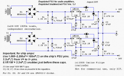
OOPS, that grounding.
The dual rectifier to separated smoothing caps works a bit differently to the single rectifier version.
Sounds like you connected the wrong wires and that caused the overheating, I hope you have not damaged something.
The output from each of the regulators is +ve and -ve.
Take one +ve to the amplifier +ve and take it's partner -ve to audio ground.
Take the other -ve to amplifier -ve and it's partner +ve goes to audio ground.
The G at far right is the audio ground and should be used as your central star ground.
don't test your amp with the input RCA disconnected. Some amplifiers oscillate when the input is opencircuit. If your tweeters are connected then new tweeters.
The input shorting plug should be used whenever you test output noise or offset. If this is completely silent then your amp is probably working well.
If you connect your source and the output becomes noisier then the source is to blame for the extra noise. Do the tests in the wrong order and it becomes difficult to work out what is coming from where.
After you connect the source you should check that output offset again, it should be unchanged.
So it appears that the slight hiss you have is from your source, forget about it, until it starts to annoy you.
OOPS, that grounding.
The dual rectifier to separated smoothing caps works a bit differently to the single rectifier version.
Sounds like you connected the wrong wires and that caused the overheating, I hope you have not damaged something.
The output from each of the regulators is +ve and -ve.
Take one +ve to the amplifier +ve and take it's partner -ve to audio ground.
Take the other -ve to amplifier -ve and it's partner +ve goes to audio ground.
The G at far right is the audio ground and should be used as your central star ground.
AndrewT said:Hi,
don't test your amp with the input RCA disconnected. Some amplifiers oscillate when the input is opencircuit. If your tweeters are connected then new tweeters.
The input shorting plug should be used whenever you test output noise or offset. If this is completely silent then your amp is probably working well.
I see, thanks! Well, the tweeters still seem to be working OK. I was doing it all very quickly though, no more than a couple of seconds. I listened for any hiss, and turned it off right away. I might have got away lucky this time I guess, but I definately shalln't be doing it again if it can potentially cause damage!
If you connect your source and the output becomes noisier then the source is to blame for the extra noise. Do the tests in the wrong order and it becomes difficult to work out what is coming from where.
This makes sense
It's definately the source making the hiss then. I might build myself a pre-amp at some point too, but for the moment lack of funds say I must use my current amp as a pre-amp After you connect the source you should check that output offset again, it should be unchanged.
Yep, no change with the source connected. Do you think it's worth while changing that 330R resistor to see if that changes anything?
So it appears that the slight hiss you have is from your source, forget about it, until it starts to annoy you.
Done and done
OOPS, that grounding.
The dual rectifier to separated smoothing caps works a bit differently to the single rectifier version.
Sounds like you connected the wrong wires and that caused the overheating, I hope you have not damaged something.
Well, it all seems to work just fine still. I've been playing it for half an hour and it's still going! I think it's ok.
The output from each of the regulators is +ve and -ve.
Take one +ve to the amplifier +ve and take it's partner -ve to audio ground.
Take the other -ve to amplifier -ve and it's partner +ve goes to audio ground.
Alright, thank you! I put some extra holes around this area so I think I should be able to do this without much of a problem if I want to do it
You have been a great help, thanks so much!
Just to let you know, changing the 100R and 2.2k to 1k and 22k did nothing for the DC offset. I guess it must be the chip?
I also get a thump, from both treble and bass drivers it seems, if I turn on / off the pre-amp while the GC is on. It sounds quite nasty! I measured the DC voltage coming from the pre-amp at about 0.300mV when this happens, though my multimeter isn't that good and I guess it could be more. The voltage at the speaker is also "only" about 0.300mV. Anything much to worry about? It sorta confused me that this DC voltage got through to the speakers, as I have an input cap. I thought this was supposed to block DC
I also get a thump, from both treble and bass drivers it seems, if I turn on / off the pre-amp while the GC is on. It sounds quite nasty! I measured the DC voltage coming from the pre-amp at about 0.300mV when this happens, though my multimeter isn't that good and I guess it could be more. The voltage at the speaker is also "only" about 0.300mV. Anything much to worry about? It sorta confused me that this DC voltage got through to the speakers, as I have an input cap. I thought this was supposed to block DC
Hi,
it'd not DC, it's a pulse.
That pulse includes some or a lot of higher frequencies in it.
The higher frequencies are not attenuated sufficiently by the filter.
You can do a variety of fixes.
The easy one is to invoke the chipamp shut down pin.
Alternatively you fit an input mute or output relay.
Since the problem is in the pre that is where you should do the fix.
A tiny signal relay supplied from one diode on the PSU bridge with a delay to the pull up voltage.
Any or all of these should be "instant off" on mains failure and "delayed on" at start up.
AndrewT said:Hi,
it'd not DC, it's a pulse.
That pulse includes some or a lot of higher frequencies in it.
The higher frequencies are not attenuated sufficiently by the filter.
Ah, that explains it. Thanks.
You can do a variety of fixes.
The easy one is to invoke the chipamp shut down pin.
Alternatively you fit an input mute or output relay.
Of course, there's also always the "don't turn the preamp on before the power amp" option too
I don't feel confident modifying this preamp really. I think I will probably soon build my own preamp though. An opamp one based on an ESP project schematic probably...Since the problem is in the pre that is where you should do the fix.
A tiny signal relay supplied from one diode on the PSU bridge with a delay to the pull up voltage.
Any or all of these should be "instant off" on mains failure and "delayed on" at start up. [/B]
Noted and noted.
A small update, I think I already mentioned I tried slightly higher resistor values to try and get the DC down, and it did nothing, so I put them back to the schematic values (and "upgraded" to 1% metal film while I was at it).
I did some heavy searching and eventually came across a thread, http://www.diyaudio.com/forums/showthread.php?s=&threadid=51214&perpage=10&highlight=&pagenumber=2, which explained things quite well. The calculations seemed to show that in order to get it to decrease I would need to go "the next step up" to 220k and 10k in the feedback.
I've just now modified the boards slightly and added a polarized
electrolytic as Ci at 470uF, and the offsets are now reduced to 3mV and 1mV. I know 470uF isn't really enough apparently, it's -3dB at 3.4Hz? And that could be out of phase all the way up to about 34Hz? I just found them laying about and decided to give it a go.Another question then: If I go up to 22k and 1k in the feedback (from 2.2k and 100R) and continue to use a 470uF, is this far too much? This would apparently be -3dB at 0.3Hz? Should I be looking at something more like 220uF (0.7Hz) or even 100uF (1.6Hz)?
I'm still waiting on my case to arrive, but I imagine I will be putting pictures of my monstrosity up soon and telling you all how impressed I am (hopefully) at the sound quality and things
AndrewT said:Hi,
why go all the way to 22k/1k?
Carlos says stay low, so try 4k3/200r with the 470uF
Ah yes, my incredible math skills are starting to show their true colours. A fantastic idea. I still get pretty much the same gain with that kind of combo too, it was just easy for me to see that moving up to 22k/1k would still give me a gain of 22, basically the only reason I suggested those

The cap I have in there is also "only" 25v aswell. I have 28.5v rails, but doesn't that cap "see" the output voltage and not the rail voltage, so this should be "adequate" and quite safe, I think?
Thanks once again Andrew!
Hi,
no, the divider action of 2k2 / 100r reduces the output AC signal back down to the same level as the input.
Remember that a power amplifier is really just an overgrown discrete opamp.
and we all know that the output of an opamp is equal to the difference between the inverting and non-inverting pins times the opamp gain.
This analogy confirms that the two sides of the LTP see almost exactly the same voltage.
HOWEVER.
if the output stage fails and pulls the output to a fixed high DC bias then the DC blocking action of the NFB capacitor ensures it sees the DC bias across it.
Two problems:
1. the inverting input is subjected to this high voltage and probably fails.
2. the cap is subjected to this DC and probably fails IF the bias exceeds it's rating (the bias could be in either direction).
To avoid both problems, some designers fit a pair of Zeners across the cap or a pair of dual diodes to limit the DC to a maximum of between 1.4V and 3.9V
- Status
- This old topic is closed. If you want to reopen this topic, contact a moderator using the "Report Post" button.
- Home
- Amplifiers
- Chip Amps
- Fuse blew