Hi,
I had just finished my LM3886 chipamp using the pcbs of chipamp.com
I thought this was an easy job compared to other projects that I finished succesfully.
However, when I switsched on power there was a huge flash at the LM3886 chip, followed by some hefty smoke.
I checked the LM3886 chip and pin 4 an 5 (looking at the front from left to right) seem to have had the shortage.
I doublechecked the connections, and also the resistorvalues, but I still have no clue. I hope someone can help me in tracing the problem.
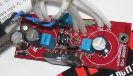
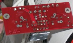
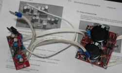
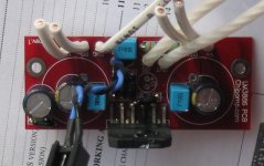
I enclose some pictures of the boards.
There are some things I thought of:
1. I did not attach the CHG from the ampboard. It should eventually be connected to the chassis, but for now I had everything running on a piece of wood.
2. I used Welwyn resistors at the amp board. They are a bit longer so I had to mount them a bit upward. I checked whether they made a shortage but this is not the case. However they present a longer path. Could it be oscillation? Could oscillation bring the hole thing to shortage in such a short moment?
3. Could it be that the LM3886 is faulty? Has anyone encountered such failures?
I am still reluctant to check whether the second mono amp is alright. I would like to pin the problem down in order to avoid the chance of frying my second LM3886...
Any suggestions are highly appreciated.
Lucas
I had just finished my LM3886 chipamp using the pcbs of chipamp.com
I thought this was an easy job compared to other projects that I finished succesfully.
However, when I switsched on power there was a huge flash at the LM3886 chip, followed by some hefty smoke.
I checked the LM3886 chip and pin 4 an 5 (looking at the front from left to right) seem to have had the shortage.
I doublechecked the connections, and also the resistorvalues, but I still have no clue. I hope someone can help me in tracing the problem.
I enclose some pictures of the boards.
There are some things I thought of:
1. I did not attach the CHG from the ampboard. It should eventually be connected to the chassis, but for now I had everything running on a piece of wood.
2. I used Welwyn resistors at the amp board. They are a bit longer so I had to mount them a bit upward. I checked whether they made a shortage but this is not the case. However they present a longer path. Could it be oscillation? Could oscillation bring the hole thing to shortage in such a short moment?
3. Could it be that the LM3886 is faulty? Has anyone encountered such failures?
I am still reluctant to check whether the second mono amp is alright. I would like to pin the problem down in order to avoid the chance of frying my second LM3886...
Any suggestions are highly appreciated.
Lucas
So you connected the + and - rails but not the ground rail to the PSU?
If so, thats your problem right there.... connect the PSU ground the the amp board's ground. Then use an earth decoupling network between the PSU ground and the case.wich in turns goes to mains earth if you have 3 prong plugs.
If so, thats your problem right there.... connect the PSU ground the the amp board's ground. Then use an earth decoupling network between the PSU ground and the case.wich in turns goes to mains earth if you have 3 prong plugs.
Nordic said:So you connected the + and - rails but not the ground rail to the PSU?
If so, thats your problem right there.... connect the PSU ground the the amp board's ground. Then use an earth decoupling network between the PSU ground and the case.wich in turns goes to mains earth if you have 3 prong plugs.
Hi Nordic,
Thanks for looking.
I checked this too.
Indeed I did not connect the CHG to chassis (since I still don't have a chassis)
However, from the PSU board there are two PG (power ground) connections that meet at the ampboard. So there is a positve voltage, a common ground and a negative voltage supplied to the amp. This is alright, isn't it?
I am still wondering whether oscillation/instabillity might cause this.
I opted for the standard configuration with just R3 (680 Ohm) and no Ci (47 uF) feedback capacitor as described on page 8 of this pdf: http://www.chipamp.com/docs/lm3886-manual.pdf
Regards,
Lucas
However, from the PSU board there are two PG (power ground) connections that meet at the ampboard. So there is a positve voltage, a common ground and a negative voltage supplied to the amp. This is alright, isn't it?
Yes it is alright. What are your voltages ?
I don't THINK oscillation would kill off straight on the flip of a switch like that....
If the power rails shorted with either the input or outpu pins it would kill it like that right away, also if you connected power the wrong way around (I have certainly done that... nowadays I keep an LED in series with a 20K resistor between the positive and negative rail to show properly working PSU.
If the power rails shorted with either the input or outpu pins it would kill it like that right away, also if you connected power the wrong way around (I have certainly done that... nowadays I keep an LED in series with a 20K resistor between the positive and negative rail to show properly working PSU.
sayang001 said:
Yes it is alright. What are your voltages ?
Hi Sayang,
I will check them tomorrow.
As you can see on the photos, I was so sure that nothing could go wrong with this "simple" propject, that I connected the the PSU and Ampboard with soldered wires, and no connectors in between. So I will have to deconnect them tomorrow.
I did check the other (100% identical) PSU board. I measured 25 Volt AC and 34 Volt DC without any load. I guess that is alright?
Regards,
Lucas
Nordic said:I don't THINK oscillation would kill off straight on the flip of a switch like that....
If the power rails shorted with either the input or outpu pins it would kill it like that right away, also if you connected power the wrong way around (I have certainly done that... nowadays I keep an LED in series with a 20K resistor between the positive and negative rail to show properly working PSU.
Hi Nordic,
Yes I know. We all make such ridiculous mistakes from time to time. With this board design, things are very straightforward. All the connections on both boards are facing each other...
Still no clue, but as I said, I will check voltages of THIS Psu tomorrow...
Regards,
Lucas
peranders said:Do you have any fuses? If yes, which values?
Hi Peranders,
I don't have any fuses other than at the iec 230Volt inlet.
I know that some people like to add fuses at their DC rails, and maybe it would have been a life saver for my LM3886 chip, but I also know that many people think they are too slow to be a lifesaver for chips... Do you think I should add one?
Today I disconnected the PSU and Amp board and measured the voltages on the particular PSU that was connected with the blown LM3886. I measured 25 AC and 33 DC on the rails. Polarities were all OK.
So it remains a mystery to me. I doublechecked all soldering points, values etc.
There remain two possibilities:
1. Might it still be oscillations that killed the chip so fast? I did not install the feedback capacitor, only the feedback resistor (22,1K) and its loop is a bit long-legged...
2. Are there any fake LM3886 around? I bought these from some source in Asia (don't remember which) and it is labelled PM14BV above the LM3886TF inscription. Or did I just catch a faulty one?
If I do not find the clue to this, I guess I will have to try the second ampboard and see whether it will smoke too. If I would insert fuses, what values would do?
Regards,
Lucas
P.S. I hope BrianGT or Peter Daniel might look into this, since both must have a lot of experience with these pcbs and LM3886 chips...
Are there any fake LM3886 around? I bought these from some source in Asia (don't remember which) and it is labelled PM14BV above the LM3886TF inscription. Or did I just catch a faulty one?
Can you make a clear picture of the front of the chip. I have experience with fake transistors from Asia ....
http://www.sayang.demon.nl/projects/sanken/sanken.html
I have some real (directly from National) LM3886TF as well to compare yours with.
http://www.sayang.demon.nl/projects/kimberly/kimberly.html
If I do not find the clue to this, I guess I will have to try the second ampboard and see whether it will smoke too. If I would insert fuses, what values would do?
Use small 24V 2w bulbs in series with + and - rails, in case of high current these will light up and limit the current. LM3886 with no load will not light the bulbs. I used this when testing with Kimberly her amplifier.
sayang001 said:
Can you make a clear picture of the front of the chip. I have experience with fake transistors from Asia ....
http://www.sayang.demon.nl/projects/sanken/sanken.html
I have some real (directly from National) LM3886TF as well to compare yours with.
http://www.sayang.demon.nl/projects/kimberly/kimberly.html
Use small 24V 2w bulbs in series with + and - rails, in case of high current these will light up and limit the current. LM3886 with no load will not light the bulbs. I used this when testing with Kimberly her amplifier.
Hi Sayang,
I cannot come that close wityh my camera to the chipamp.
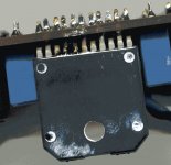
I enclose one photo from above and one made with my scanner of the backside of the chip where one can see the damage.
Regards,
Lucas
Attachments
I cannot come that close wityh my camera to the chipamp.
Desolder the chip from the pcb and put it on the scanner with it's front, it is broken anyway

Lucas_G said:
1. Might it still be oscillations that killed the chip so fast? I did not install the feedback capacitor, only the feedback resistor (22,1K) and its loop is a bit long-legged...
OMG, i am not familiar with the board, but it looks like you skipped the dc-blocking cap instead of shorting it. This makes the amp unity gain and oscillate like hell.

Why do you simply skip parts ?

Mike
sayang001 said:
Desolder the chip from the pcb and put it on the scanner with it's front, it is broken anyway
You are right. I will do this this evening...
MikeB said:
OMG, i am not familiar with the board, but it looks like you skipped the dc-blocking cap instead of shorting it. This makes the amp unity gain and oscillate like hell.
Why do you simply skip parts ?
Mike
Hi Mike,
The reason can be found here:
I opted for the standard configuration with just R3 (680 Ohm) and no Ci (47 uF) feedback capacitor as described on page 8 of this pdf: http://www.chipamp.com/docs/lm3886-manual.pdf
I checked the pcb. The 22,1 kOhm resistor is connected!
Regards,
Lucas
Lucas_G said:
Hi Mike,
The reason can be found here:
I opted for the standard configuration with just R3 (680 Ohm) and no Ci (47 uF) feedback capacitor as described on page 8 of this pdf: http://www.chipamp.com/docs/lm3886-manual.pdf
I checked the pcb. The 22,1 kOhm resistor is connected!
Regards,
Lucas
Sorry Lucas, my fault. I should not post not knowing the pcb...
But, you might check the soldering next to r3, the "SG" point. It looks like the pad on the bottom is broken. In this case you would get the same result, oscillation.
It just looks suspect on the photo...
Mike
- Status
- This old topic is closed. If you want to reopen this topic, contact a moderator using the "Report Post" button.
- Home
- Amplifiers
- Chip Amps
- Smoking Chipamp