There's a few threads on here about building a soft start circuit (something which seems to have been overlooked seemingly everwhere?), but I was searching google and came across http://www.diyhifi.org/forums/viewtopic.php?t=369
This one looks within my "construction abilities", but I was just wondering if anyone could see anything clearly wrong with it? If I do build it would it be better to have three 270R 5W resistors (= ~90R?) in parallel rather than two 47R 5W resistors (= ~90R?)? I would have thought that in series the first resistor would be taking most of the heat, whereas with parallel it gets spread out evenly between the three? No?
Any input or easy alternatives would be much appreciated!
Hi,
whether parallel or series makes no difference when the resistor values and permitted power dissipations are the same.
BUT, in my opinion the thinner wire in a 270r resistor compared to a 30r (if you can find one) will be less tolerant of overload. I would use series connected, to allow the more robust thicker wire.
three //270r 5W = 90r 15W
three series 30r 5W = 90r 15W
You live in 230 V country.
If your wall fuses are 10 A, then the max inrush current should be max 10-15 A under 100-200 ms.
Worst case conditions are (230 x 1.4)/10 = 32 ohms
Short term power is then 3200 W
but....
if you have 100 ohms 4-5 W rating, delay time of 300-600 ms for a 600 VA transformer, the resistor _will_ last. For me it has worked every day since 1988! Rather many of my softstarter are built with 100 ohms and I have never heard about any failure.
You may increase the power rating if you have huge smoothing caps. I have 600 VA, 2 x 63 VDC, 44000 uF per rail and a 100 ohms/4 W resistor.
With 100 ohms you will get 3,2 A max.
It's nothing wrong with higher power rating but 4-5 W is enough according to practical experience.
When it comes to transient capability I'll agree with Andrew, better to connect in series but hardly any problem here.
Thanks both for your input! I never thought about the fact that 270R resistors will have thinner wire (makes sense!). I'll stick with the two 47R's as on the schematic then.
As for delay, how might I figure out what kind of delay that schematic is giving me?
I have also come across something by Rod Elliot: http://sound.westhost.com/project39.htm The first schematic on there looks quite simple too. I'm not sure about either designs at the minute though, as the PCB on Mr Elliots website actually uses a different circuit. I don't suppose anyone here has built Rod's first schematic, the one using the MOSFET?
If you are using a LM3886, National Semiconductor has you covered already. From the list of features in the spec sheet :
God bless op-amp IC designers
Supply under-voltage protection, not allowing internal
biasing to occur when |VEE| + |VCC| ≤ 12V, thus
eliminating turn-on and turn-off transients
God bless op-amp IC designers
munchkin said:If you are using a LM3886, National Semiconductor has you covered already. From the list of features in the spec sheet :
Has anyone tried using an electrolytic on the mute pin for a soft turn-on for the Lm3886? Seems I saw that in one of Nationals applications notes? I thought it might be good for having the amp slow start after a power outage, which is a semi regular occurance where I live.
I just received my parts and have started building my first chip amps; I was thinking about trying this approach. Does anyone have any experience with it and are there any sonic penalties?
Regards, Mike
I'm trying it at the moment in an active set up to mute the noise of the crossover starting up. The only issue I have found is that with the relatively low rails, (15V), I'm using I have to use a 2200uF cap to get a long enough delay whilst keeping the resistance low enough to sink enough current. I may well go down the route of using a RC delay to drive a transistor and relay simply to make it a little more straightforward.
pinkmouse said:Unless your traffo is over 500VA or so, or you have a huge, (30-40K uF) capacitor bank, then you should be fine without a softstart.
I've heard 300VA and onwards, and the power around here doesn't seem all that brilliant... so I want to be on the safe side.
AndrewT said:three //270r 5W = 90r 15W
three series 30r 5W = 90r 15W
three series 30r 5W = 90r 5W not 15W
Cheers
pinkmouse said:The only issue I have found is that with the relatively low rails, (15V), I'm using I have to use a 2200uF cap to get a long enough delay whilst keeping the resistance low enough to sink enough current. I may well go down the route of using a RC delay to drive a transistor and relay simply to make it a little more straightforward.
Since the transformer I have will provide me with approximately +/- 36vdc and I only need maybe 5 seconds it sounds like I should be able to make it work... I think I'll plan on a leaving a bit more room availible based on your experiences. Thanks for the input.
Regards, Mike.
pinkmouse said:Well, I've never had a problem with any of mine. Bear in mind, most of those recommending 300VA are on 110V mains, therefore have twice the current to start with.
Aaaaaaah that might explain it then. Sort of a relief to hear in a way. Does the inrush current not stress caps and things still though?
I will probably be ordering the parts to build my first GC (or any amp for that matter) tomorrow or the day after hopefully. Can't wait!
I think the soft start circuit's purpose here is not for the amp which has it's own thump protection, but to reduce stress on the rectifier diodes and the power switch, prolonging their lives.
It also allows use of a faster blow or lower current fuse to protect everything. If you have a huge capacitor bank and the fuse is sized to handle the huge inrush current at power-on, it may be too big to protect your speakers from a failing amplifier or the power transformer from a failing capacitor.
I_F
fyi
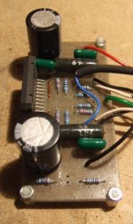
That soft start circuit looks similar to the one I did, based on the ESP project. See here:
http://www.parttimeprojects.com/audio/diy/SoftStartwebpage.html
If you can find a free copy of a circuit simulator, you can emulate the circuit, its really fun.
That soft start circuit looks similar to the one I did, based on the ESP project. See here:
http://www.parttimeprojects.com/audio/diy/SoftStartwebpage.html
If you can find a free copy of a circuit simulator, you can emulate the circuit, its really fun.
You'll need a soft starter for three reasons:markiemrboo said:
I've heard 300VA and onwards, and the power around here doesn't seem all that brilliant... so I want to be on the safe side.
1 Your fuses in the wall blows now and then (irritating)
2 The mains switch has problems with the life time
3 The rectifier may be a bit weak for the applicaton and is stressed over it's limits.
I would say the main reason is no. 1. If the fuse doesn't blow and the mains switch survive, you haven't got a problem.

As Andrew says below, with a softstarter it's possible to tune the internal mains fuse to a more "protective" value.
Hi,
the big advantage of a soft start with toroidal transformers is the ability to close rate the mains fuse to operating conditions instead of a fuse that survives the start up surge. Use about 200 to 300mS delay on the relay.
If you want to slow down the capacitor charging and/or reduce the current pulses through the rectifiers then use a different circuit.
What you should be using on the SECONDARY is a power thermistor that reduces the peak current and adjusts it's resistance to suit the load. For best performance the thermistor should be shorted out of circuit after a long delay. I think it will depend on the circuit values but somewhere around 5seconds should suffice.
- Status
- This old topic is closed. If you want to reopen this topic, contact a moderator using the "Report Post" button.
- Home
- Amplifiers
- Chip Amps
- Soft start circuit for GainClone