I've actually been drawing PCB's with the freeware version of Eagle as I am thinking about giving it a go. I got the soft-start circuit working on stripboard, but meh.
Just read today about the Hydrochloric Acid + Hydrogen Peroxide method, which I was going to try if I can find it. Does this method work well with PCB etch resist pens? I assume it will?
The only thing holding me back at the minute is that the PCB boards I have are Fibreglass.... and apparently they eat "normal" drill bits for breakfast Possibly more money for the right drill bits, or get some "normal" PCB boards... hm
Just read today about the Hydrochloric Acid + Hydrogen Peroxide method, which I was going to try if I can find it. Does this method work well with PCB etch resist pens? I assume it will?
The only thing holding me back at the minute is that the PCB boards I have are Fibreglass.... and apparently they eat "normal" drill bits for breakfast
Possibly more money for the right drill bits, or get some "normal" PCB boards... hmYeah well you are not going to get hundreds of holes drilled... i.e. buy more than one, they are cheap... I get 2 for the equaivalent of about a dollar... and break at least 2 per project... no killer...
Once again... I want to stress how much better ferric chloride will work, and how much safer it is... also yuo don't have to keep on adjust ing the mixture etc... actualy the HCL and peroxide works out more expensive in the even short term....
I'm a litle too lazy now to take paictures... but I sometimes, just print from eagle onto paper... tape it to the pcb... drill all the holes throughboth the paper and board using the paper as the template... then take off the paper and play connect the dots with your black marker after that its straight into the ferric chloride.
Nordic said:Yeah well you are not going to get hundreds of holes drilled... i.e. buy more than one, they are cheap... I get 2 for the equaivalent of about a dollar... and break at least 2 per project... no killer...
Once again... I want to stress how much better ferric chloride will work, and how much safer it is... also yuo don't have to keep on adjust ing the mixture etc... actualy the HCL and peroxide works out more expensive in the even short term....
I'm a litle too lazy now to take paictures... but I sometimes, just print from eagle onto paper... tape it to the pcb... drill all the holes throughboth the paper and board using the paper as the template... then take off the paper and play connect the dots with your black marker after that its straight into the ferric chloride.
Adjusting the mixture? No one mentioned that in my searches
Just how quickly it etched and the fact it could do it at room temperature. If I go for ferric it probably will end up costing me more, as I doubt anywhere local has it (tiny village, small town, rather rural area).... which means postage costs! Dah! I'll think about buying it over the next few hours then As far as PCB's go..... i'm REALLY confused about this 'star grounding' scheme. I just don't get it at all actually. I've basically separated the power ground's from the signal grounds, and separated the input and output grounds, and put a pad on each ground trace where I would then run a wire back to some pads at the power connector. Is this the right idea?
Attachments
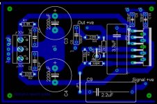
Well the whole point to is a star is SEPERATE returns to ground... i.e. more like the example I attach and less like the one you did... yes, you can seperate the signal and power ground if you want, some of the methods are to use 0 ohm resistors, beads, thin wire etc... I think its all relative... i.e. sufficiently thin trace in comparison to other ground traces met will influence the path of least resistance for ground...
Nordic said:Well the whole point to is a star is SEPERATE returns to ground... i.e. more like the example I attach and less like the one you did... yes, you can seperate the signal and power ground if you want, some of the methods are to use 0 ohm resistors, beads, thin wire etc... I think its all relative... i.e. sufficiently thin trace in comparison to other ground traces met will influence the path of least resistance for ground...
Probably being incredibly dense, but I still don't get it. You say that it's supposed to mean separate returns to ground, which..... is what I was originally doing I thought? In that picture it looks to me like you joined them back up again... and unseparated them?

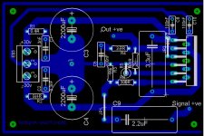
I think I just need a better picture of what I should be aiming for. Should I be aiming for the 'ground current', or whatever, from the power section to flow towards pin 2 of my power connector rather than towards the chip? So a big fat trace connecting to pin 2 and a much thinner trace from there towards the chip? Something like the attached? But then if the wire on the power connector has a bigger resistance than the thin trace towards the chip it would flow there instead wouldn't it?
Thanks for your help
I'm such a n00blet! 
Attachments
I was returning all the grounds to a signal star ground.. this in turn gets connected to your power star ground...
All the points on one trace as you have it are not equal grounds, and there is minute voltage difirences between them. Bringing them to one point solves this problem and "cleans up" the signal ground.
All the points on one trace as you have it are not equal grounds, and there is minute voltage difirences between them. Bringing them to one point solves this problem and "cleans up" the signal ground.
Nordic said:I was returning all the grounds to a signal star ground.. this in turn gets connected to your power star ground...
All the points on one trace as you have it are not equal grounds, and there is minute voltage difirences between them. Bringing them to one point solves this problem and "cleans up" the signal ground.
When you say power star ground do you mean the blob of pads that was to the left of my power connector? So a single wire would run from the big capacitor blob pad over to there? Or something completely different?
Oh an also, the jumper on the signal going over the -30v power trace, would it be better to have this the other way around, so the jumper is on the power trace going over the signal trace?
A isolated power rail by itself is not ideal....
+V| = bad
+V||0V = better
I.e. running a ground trace next to a power trace ... by which time you would have created most of a proper ground plane.
I guess you can take a chance with crossing that rail, but its quite a high current one.... maybe you can pass the power rail around the input cap rather... althoug its still bad being without a decoupling rail...
Nordic said:A isolated power rail by itself is not ideal....
+V| = bad
+V||0V = better
I.e. running a ground trace next to a power trace ... by which time you would have created most of a proper ground plane.
I guess you can take a chance with crossing that rail, but its quite a high current one.... maybe you can pass the power rail around the input cap rather... althoug its still bad being without a decoupling rail...
Decoupling rail? Power trace next to a ground trace? Isolated power rail? I don't understand any of that either

I just got rid of the jumper by running the trace under the cap, didn't think of that. Here's what I have so far... I still don't get the whole grounding thing either
When you said power ground before, was that the same as "earth ground"?
Attachments
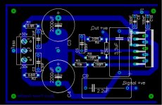
Alright, I did some reading ( finally found a site which I can semi-understand-ish: http://www.paulrubyamps.com/info.html#StarGround ) and went back to the schematic I am using. From what I understand the following should be on the right tracks? It's separated the input, output and power and then each one would go back to a point on the power supply PCB, the ground point of the first capacitor, just after the bridge rectifier? Then that point on the PCB would connect to the case via a single wire? Or do the individual points that I have drawn just go straight to the case star ground point?
EDIT: forgot to attach "the following"
EDIT: forgot to attach "the following"
Attachments
- Status
- This old topic is closed. If you want to reopen this topic, contact a moderator using the "Report Post" button.
- Home
- Amplifiers
- Chip Amps
- Building my first "Gainclone"