Hi,
I am not too good at interpreting these chipamp schematics, but I think I see a problem. Please confirm or argue or whatever.
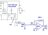
The input to the inverted chipamp will see 10k + the slider resistance as it's source resistance (it will also see the 1M in parallel but in this case it is insignificant). The source resistance will vary with slider position. The gain will vary with slider position. So far no problem.
The source resistance varies from 10k (when slider is at maximum attenuation) to 110k//1M (when the slider is @ 0db).
The DC output offset will vary with the differing source resistance as the volume attenuator is swung through it's operating range. Problem?
How much will the output offset vary with attenuation?
BTW.
the output capacitor will see the 1M @ the source end of the connector in parallel to the 100k attenuator and a varying resistance of 10k to nearly infinity also in parallel.
The cap therefore sees about 9k to 90.1k after the 470nF and the cutoff frequency (-3db) will vary from 37.6Hz to 3.76Hz.
About -1db from 75Hz @ 0db and 7.5Hz @ -70db. So much for direct coupling. Even -1db @ 7.5Hz will be audible as loss of bass.
Understand the theory and consider the conditions from source to output (not just the amp in isolation).
I am not too good at interpreting these chipamp schematics, but I think I see a problem. Please confirm or argue or whatever.
The input to the inverted chipamp will see 10k + the slider resistance as it's source resistance (it will also see the 1M in parallel but in this case it is insignificant). The source resistance will vary with slider position. The gain will vary with slider position. So far no problem.
The source resistance varies from 10k (when slider is at maximum attenuation) to 110k//1M (when the slider is @ 0db).
The DC output offset will vary with the differing source resistance as the volume attenuator is swung through it's operating range. Problem?
How much will the output offset vary with attenuation?
BTW.
the output capacitor will see the 1M @ the source end of the connector in parallel to the 100k attenuator and a varying resistance of 10k to nearly infinity also in parallel.
The cap therefore sees about 9k to 90.1k after the 470nF and the cutoff frequency (-3db) will vary from 37.6Hz to 3.76Hz.
About -1db from 75Hz @ 0db and 7.5Hz @ -70db. So much for direct coupling. Even -1db @ 7.5Hz will be audible as loss of bass.
Understand the theory and consider the conditions from source to output (not just the amp in isolation).
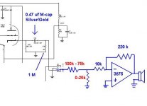
F (-6dbV) = 1 / ( 2 pi R C ) [R in Ohms, C in Farads, F in Hertz]
C = 0.47 x 10^-6
When the pot is at very very low settings
R = 1 x 10^6 || 1 x 10^5 = R1 R2 / (R1 + R2 ) = 90909
F = 1 / ( 2 x 3.14159 x 90909 x 0.47 x 10^-6 )
= 3.72 Hz
When the pot is at highest setting
R = 1 x 10^6 || 1 x 10^5 || 1 x 10^3 = 9009
F = 1 / ( 2 x 3.14159 x 9009 x 0.47 x 10^-6 )
= 37.6 Hz
This is a seriously flawed design because the inverter input resistor Ri is much lower than the pot and so the low frequency roll-off changes dramatically as the pot is adjusted. The roll-off frequency is also too high at normal volume settings.
You can keep the 0.47uF output cap if you add a buffer opamp between the pot wiper and the 10K resistor.
An alternative is the increase the cap to say 4.7uF and change the 100K pot to 10K. This will give F low volume = 3.39 Hz, F high volume = 6.77 Hz. Just make sure the cathode follower works OK into a 5K load.
HTH.
Hi All,
Thanks for your advise.
I'm using ladder type stepped atten' and here this the value of R in my normal listening range.
For my system, I never turn them over the 3pm position, that's 75k and 25k. ( normal listening level is 95k and 5k ). If my calculation is not wrong this will give feq. cut off below 10 Hz, is this seems to be alright ?
Attachments
Hi,
you have a very effective variable high pass filter between the source and amplifier.
It would be a better design if you could eliminate the variable part and I suggest you take the high pass roll off down by one or two octaves or better still, three octaves lower.
The design as you have it, is poor.
- Status
- This old topic is closed. If you want to reopen this topic, contact a moderator using the "Report Post" button.
- Home
- Amplifiers
- Chip Amps
- Fequency cut-off for Direct coupling GC