From AndrewT
C'mon guys - lighten up a little
We are not ADDING the two 38.5 together, this is a BIPOLAR supply. Each side is 38.5v.
Taking one side as a simple example:
38.5v AC secondary is peak voltage. into a bridge (full wave) rectifier produces RMS DC of 33.87V, when the 3% ripple is smoothed by the caps, the result is about 34.2V DC.
Respectfully, I think you fellows are confusing peak AC and RMS.
John65b - would you like a schematic or photos?
+-34Vdc from 2*38.5Vac is not possible. Ignore that poster until he can prove his assertion.
C'mon guys - lighten up a little
We are not ADDING the two 38.5 together, this is a BIPOLAR supply. Each side is 38.5v.
Taking one side as a simple example:
38.5v AC secondary is peak voltage. into a bridge (full wave) rectifier produces RMS DC of 33.87V, when the 3% ripple is smoothed by the caps, the result is about 34.2V DC.
Respectfully, I think you fellows are confusing peak AC and RMS.
John65b - would you like a schematic or photos?
JesseG,
Please post pics and schematic anyway...it would be good to see you system regardless of what the nomenclature diffences are...
I will most likely unwind the trannie as Poobah instructed (Thanks Poobah).
But just for S&G, why couldn't wire up 40V & 0V to a rectifier to get same results as 20V 20V? Understand that I won't do it, but my curiosity won't let this go...
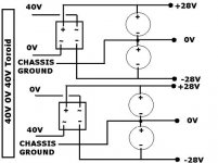
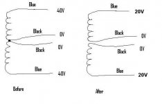
So this can work? Wow... remember, I have two centertaps (black wires), and two 40V leads (blue wires)... and all four wires, (blue, black, black, blue) are the same winding...voltage across any blue to any black is 40V....blue to blue is 80V, etc.
And the virtual ground (0V) between the pair of smoothing caps is made by a single connection to chassis ground and nothing else...
Don't understand the bleeder resistor issue...attached is a schematic...
So if anyone has a high voltage centertap trannie (CT needs to be split), they can do this to get something that is identical to two separate trannies at 1/2 the voltage for a dual mono power supply??
Attachments
Yep...
Place bleeder resistors in parallel with each cap such that they burn 3 to 5 Watts. The resistors should be 1 or 2% as they will ultimately determine the balance between rail voltages.
Me... I would unwind the the tranny. But I am unclear as to your tranny wiring. Can you make a picture?
What you have drawn presumes 2 isolated windings, but you describe all 4 wires as being "the same winding".
I get 0 ohms between both black wires - there is only one winding. The two centertaps are the same.
In other words, if I had a centertap tranny (three wires) and I took the centertap wire and split it, so there are now four wires, this is what I have
I do not know why the manufacturer of this torroid split teh centertap, but it is the same wire.
Knowing this, would this still work? I have tried it a while back I remember it working....
Hi,
although I said rewind the toroid, you do not need to unwind all of the secondaries.
Find a point about midway along each winding. Cut the two windings at about the mid-points.
Measure the voltage in each of the four new shorter windings.
Add turns to each to bring them up to the desired voltage.
Now you can run four windings into two recifiers to give two dual polarity supplies, one for each channel or you can parallel two windings to double the current capacity and end up with one dual polarity supply.
Buy some enamelled copper wire of the same diameter as you have on the secondaries.
By adding turns the total VA rating is not reduced. Some would argue that the VA rating is slightly increased.
If you reduce the turns on the secondary then the VA rating is reduced in proportion to the reduced voltage you end up with. i.e. the current stays the same.
Do you follow all that?
VA rating is perhaps not a good way to look at this. VA is really is power rating, based on an optimal design, that proiduces a given temperature rise. That is 50% iron loss, and 50% copper loss.
Reducing turns could be viewed as reducing VA, because of the obvious loss in voltage. But also winding resistance decreases, in turn heat. The flip side, increasing turns, does not increase VA. You have the same core and iron losses, but more winding resistance. Bottom line is that winding currents should be considered priority over VA. Regardless, removing turns, can be done safely without concern, as long as the winding current is not proportionately increased by presuming the VA remains equal.
John,
The decision to unwind should really be made based on whether the secondaries are wound side by side (good thing)... or one on top of the other (bad thing). To implement the drawing you have would require that the center taps be split anyway. How about pulling away some tape and checking the lay of the windings?
")
Reducing turns could be viewed as reducing VA, because of the obvious loss in voltage. But also winding resistance decreases, in turn heat. The flip side, increasing turns, does not increase VA. You have the same core and iron losses, but more winding resistance. Bottom line is that winding currents should be considered priority over VA. Regardless, removing turns, can be done safely without concern, as long as the winding current is not proportionately increased by presuming the VA remains equal.
John,
The decision to unwind should really be made based on whether the secondaries are wound side by side (good thing)... or one on top of the other (bad thing). To implement the drawing you have would require that the center taps be split anyway. How about pulling away some tape and checking the lay of the windings?
Andrew, I think I understand...I will look at the winding tonight if possible.
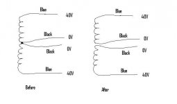
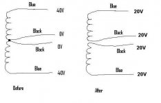
I suspect both black centertaps are connected at the same point on the winding. If I cut the winding at that point, I create two separate windings, and thus a dual secondary. No unwinding, or rewinding would be nessessary...see my attachment...
From there it becomes as simple as connecting the power supply with dual secondaries.
Attachments
=as long as the winding current is not proportionately increased by presuming the VA remains equal.
If you reduce the turns on the secondary then the VA rating is reduced in proportion to the reduced voltage you end up with. i.e. the current stays the same.
More likely you have 2 windings pulled side by side. The virtual ground technique is less than ideal... avoid it if you can.
Andrew,
Therein lies the confusion, or lack thereof... as you remove turns, you shorten the winding and decrease its reisistance. Depending on the intitial current density in the winding; some increase in winding current is acceptable. My point being is that VA rating, in an optimal design, is a function of surface area and allowed temperature rise. When turns are altered, optimal goes out the window... as should VA ratings.
Would two windings pulled side by side indicate continuity between the two black 0V leads? I also have continuity between the two blue 40V leads....
I currently have one 40V 0V 40V 400VA toroid up for trade for a 22V 0V 22V 300VA or better on diyaudio. This is my first option. Next is to unwind/modify the toroid, and third is to try something crazy like I have drawn up.
I currently have one 40V 0V 40V 400VA toroid up for trade for a 22V 0V 22V 300VA or better on diyaudio. This is my first option. Next is to unwind/modify the toroid, and third is to try something crazy like I have drawn up.
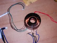
OK... now you'll see how a center is created from 2 coiuls wound
at the same time.
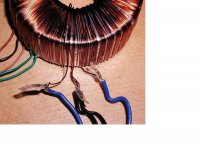
Look closely and you will see one blue and one black that start/end at the same point. The other black and blue will lead off to another point. All you have to do is find the pairing and unwind both coils at the same time. Separate the coils. take some measurements... derive a volts per turn and go to town.
Remember to leave you voltage about 5-10% high. of target.
BTW... what are all the other windings?
at the same time.
Look closely and you will see one blue and one black that start/end at the same point. The other black and blue will lead off to another point. All you have to do is find the pairing and unwind both coils at the same time. Separate the coils. take some measurements... derive a volts per turn and go to town.
Remember to leave you voltage about 5-10% high. of target.
BTW... what are all the other windings?
- Status
- This old topic is closed. If you want to reopen this topic, contact a moderator using the "Report Post" button.
- Home
- Amplifiers
- Chip Amps
- Transformer question for Chipamp...