Hi,
http://www.rapidonline.com/netalogue/specs/34-0635.pdf
I was thinking about using copper track on matrix board to build a pcb for a Gainclone. To change track direction I would need to solder at the joint. Then maybe some lacquer after completion.
However, I'm unsure what current these tracks could handle, and is the peel adhesion enough ?
An externally hosted image should be here but it was not working when we last tested it.
http://www.rapidonline.com/netalogue/specs/34-0635.pdf
I was thinking about using copper track on matrix board to build a pcb for a Gainclone. To change track direction I would need to solder at the joint. Then maybe some lacquer after completion.
However, I'm unsure what current these tracks could handle, and is the peel adhesion enough ?
I have used this stuff before for simple circuits in college and for repairing tracks on damaged pcb's.. its very handy stuff to have around.. I actually built a constant current battery charger for chargeing r/c car batteries from a 12V supply useing just self adhesive copper tracks and a few sheets of perspex in college, made a box out of perspex and built the circuit on another piece of perspex useing this stuff and stuck the perspex in like a shelf inside the box, looked really cool and worked well.. not sure about how long the adhesive will hold for under normal operateing conditions though but it was a pain in the *** because i had to solder everythign before i stuck it to the perspex and it was more for show than actuall use, was one of my projects i had to do for my HND.
Owen
Owen
ash_dac said:I was thinking about using copper track on matrix board to build a pcb for a Gainclone. To change track direction I would need to solder at the joint. Then maybe some lacquer after completion.
However, I'm unsure what current these tracks could handle, and is the peel adhesion enough ?
Hi ash_dac,
As mentioned in the pdf, this is also used for stained glass. It is available in various widths and may be cheaper bought through stained glass suppliers.
regards
Re: Re: Self adhesive copper track Gainclone
In a normal pcb how is the copper bonded to the circuit board ?
I'm not too sure if I used matrix board that the track would stick to the board due to the holes. Once soldered I guess it would hold together. But would the components be under strain ?
Greg Erskine said:
Hi ash_dac,
As mentioned in the pdf, this is also used for stained glass. It is available in various widths and may be cheaper bought through stained glass suppliers.
regards
In a normal pcb how is the copper bonded to the circuit board ?
An externally hosted image should be here but it was not working when we last tested it.
I'm not too sure if I used matrix board that the track would stick to the board due to the holes. Once soldered I guess it would hold together. But would the components be under strain ?
Hi ash_dac,
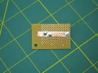
I can't answer all your questions but as I had all the bits on hand I did a little experiment, see picture.
It definitely sticks to the protoboard.
The stuff I used seems a little thin, but should still work OK.
At one end, I applied the soldering iron to see what happens when it gets very hot. The glue seems to let go around the edges but it didn't lift right off.
So its probably worth experimenting with.
regards
Attachments
Hi,
the soldered legs will hold it in place. The proto board then just acts to hold the components and copper strips in their rightful places.
You can fold the copper strip at the corners. Do not cut it!
Fold it round to the angle you want. Lift the excess up to a point, press the flat strip down into the board and then fold the sticky up bit over on top of the flat strip. You can even sweat some solder into the two adjacent faces.
Hi
You will have trouble with the LM**** pin pitch using that matrix board from Maplin.You will have to bend some pins of the LM**** to fit the holes.
Sorry to throw water on your idea but why not just buy yourself a couple of metres of CT100, and use the inner conductor to hard wire the components together.
AndrewT said:Hi,
single core 0.6mm is ideal for all the low to medium current interconnections. Very short lengths (<5mm) left without insulation. Longer lengths with insulation kept on. Colours help trace the circuits workings.
With regards to this should I take a length of wire run it underneath the matrix board, coiling it around component leads as necessary, and then solder ?
Hi,
you will probably find under board is easier (just like tracks) but it depends on how busy it gets. Be flexible.
A 90degree bend is probably secure enough. Doing more (180degrees) makes it more difficult to make changes.
If the wire is very short just touching the side of a component leg will be enough to get a secure solder joint.
CHIPamp works of art
Hi,
I have seen some direct to pin build photos.
They look very effective and are often works of art that any builder would be pround of.
Try a slightly higher iron temperature. It will allow faster working and not put any more total heat into the pins.
Hi,
I have seen some direct to pin build photos.
They look very effective and are often works of art that any builder would be pround of.
Try a slightly higher iron temperature. It will allow faster working and not put any more total heat into the pins.
ash_dac said:Hi,
Is soldering components to LM3886 bad practice?
In the past I have tried soldering to IC's but have struggled to get good joints due to the IC package dissipating soldering iron heat.
Some would say its the prefered way.... never had a problem soldering anything to a chipamp pin... not one of those stupid pins that is like oil and water whern you show it hot solder.
Nordic said:
Some would say its the prefered way.... never had a problem soldering anything to a chipamp pin... not one of those stupid pins that is like oil and water whern you show it hot solder.
Hi,
...Make the ground pin long, and solder to a metal ground wire. I'm not exatly sure how to layout the grounding.
Decoupling:- As pin 8 is connected to V- through a resistor. Can pin 8 be used as V- decoupling point ? (Pin 8 is decoupled in the datasheet but so is the V- supply. Decoupling pin 7 to 8 would be much easier and looking at the -PSRR might be worthwhile.
An externally hosted image should be here but it was not working when we last tested it.
An externally hosted image should be here but it was not working when we last tested it.
Hi,
correct grounding practice is crippled by the internal layout of most chipamps.
To help alleviate this inherent problem, the external grounding must be exemplary.
UNDERSTAND the requirement first, then design the layout to achieve the desired result.
Don't just blunder in and hope that big ground wires connecting every zeroVolt reference in random order will be successful.
AndrewT said:Hi,
correct grounding practice is crippled by the internal layout of most chipamps.
To help alleviate this inherent problem, the external grounding must be exemplary.
UNDERSTAND the requirement first, then design the layout to achieve the desired result.
Don't just blunder in and hope that big ground wires connecting every zeroVolt reference in random order will be successful.
Thanks for the tips.
Any grounding /pcb book recommendations ?
I suppose NS might supply the internals
Originally posted by AndrewT
Try a slightly higher iron temperature. It will allow faster working and not put any more total heat into the pins.
Wouldn't it be the soldering irons wattage that would be the main factor here?
And I thought ICs were really sensitive to heat, on projects I have worked on in the past involving ICs, there have been warning about heat going into ICs and some have even requested little IC heatsink clamp thingies.
Cheers, Nic.
Hi,
most semis specify 300degC for 10seconds maximum.
If you delay by trying to heat up a pin with too low a tip temperature then heat transfers to the internals and risks damage.
If you can get a succesfull joint at 330degC in 5 seconds you end up with LESS heat inside the semi and less risk of damage. But you must be quick.
- Status
- This old topic is closed. If you want to reopen this topic, contact a moderator using the "Report Post" button.
- Home
- Amplifiers
- Chip Amps
- Self adhesive copper track Gainclone