Hi,
we all know that GC sounds much better with a buffer. There are many good buffer circuits circulating but most of them are discrete. Many beginners are reluctant to go in for a discrete circuit, even the simple ones with 2 or 3 transistors. One month ago the company that I work for received a lot of (hundreds) sample Op Amps from local AD, LT and TI dealer. Having the opportunity, I did a lot of testing and experimenting with these Op Amps as buffers.
The goal was to find the Op Amp that will (apropriately implemented) have:
- best sound possible
- the least DC offset possible (to avoid the use of coupling cap)
- easiest implementation
- ability to drive loads as low as 1K
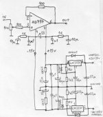
The winner is AD797. Sound is wonderfull, no objections at all. DC offset on output is less than 0.1 mV. The circuit is reasonably simple. Drives 600 Ohms load with ease.
Don't ask me for layout, I built it point to point.
Schematic of the buffer and PS is at the end of the post.
Have fun !
we all know that GC sounds much better with a buffer. There are many good buffer circuits circulating but most of them are discrete. Many beginners are reluctant to go in for a discrete circuit, even the simple ones with 2 or 3 transistors. One month ago the company that I work for received a lot of (hundreds) sample Op Amps from local AD, LT and TI dealer. Having the opportunity, I did a lot of testing and experimenting with these Op Amps as buffers.
The goal was to find the Op Amp that will (apropriately implemented) have:
- best sound possible
- the least DC offset possible (to avoid the use of coupling cap)
- easiest implementation
- ability to drive loads as low as 1K
The winner is AD797. Sound is wonderfull, no objections at all. DC offset on output is less than 0.1 mV. The circuit is reasonably simple. Drives 600 Ohms load with ease.
Don't ask me for layout, I built it point to point.
Schematic of the buffer and PS is at the end of the post.
Have fun !
Attachments
juma said:Hi !
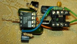
Here is a pic of this buffer made point-to-point, together with OPA1632 differential line driver.
smart
")
hi, juma !
i have build a non-inverting gainclone with one lm3886 chip without any input buffer or something...
in my opinion the sound is already good.
would it be an improvement if i add your buffer?!
on what value should i set the gain of my lm amplifier, if i use your schematic?
sorry for my english
i have build a non-inverting gainclone with one lm3886 chip without any input buffer or something...
in my opinion the sound is already good.
would it be an improvement if i add your buffer?!
on what value should i set the gain of my lm amplifier, if i use your schematic?
sorry for my english
Hi Mick !Mick_F said:You dont want any resistor to ground at the input?
Mick
As you can see on the schematic, input is ground referenced through potentiometer. Nice site Mick, I like your p2p work.
bjoern said:hi, juma !
i have build a non-inverting gainclone with one lm3886 chip without any input buffer or something...
in my opinion the sound is already good.
would it be an improvement if i add your buffer?!
on what value should i set the gain of my lm amplifier, if i use your schematic?
sorry for my english
Hi Bjoern !
You are right, LM3886 sounds good even without buffer, but in everyone's experience it sounds better with buffer. Of course, you should have equally good sound source and loudspeakers to fully comprehend the improvement.
If you decide to build this buffer you shouldn't change the gain of you GC. Buffer does not amplify the input signal's voltage. It amplifies the current, actually it's a mean to adjust the output impedance of signal source to input impedance of amplifier.
Dein englisch ist gut genug, lass uns die Verstaerker machen
Hi Juma,
I have seen that it is ground referenced through the pot but I was wondering if this suffices as this reference changes with the pot setting and is rather low - only 10k when the pot is fully open and at normal listening levels it will be much less. But maybe that works nevertheless just fine for this buffer.
Also, how does this buffer compare to the simple discrete JFET buffer you recently compared?
Cheers,
Mick
Hi,
the10k provides two DC routes for current to ground.
One route is direct to ground through the lower half of the pot.
The other through the upper half of the pot then flows to the input RCA , on to the output stage of the source.
If the Source is low impedance then both routes are effectively in parallel. However often the source is over 600ohms and may also have a DC blocking capacitor on the output.
The maximum AC impedance to ground is about {pot value+source impedance}/4 including the small correction for source impedance.
If a DC blocking capacitor is fitted then the DC resistance to ground does indeed vary with the pot value.
Juma,
If the pot goes open circuit the non inverting input hangs floating with almost infinite impedance on the pin. It would be slightly better to add a high value resistor from the non-inverting input to ground (about 2 to 10 times the pot value) It would be even better to add a small capacitor to limit the high frequency rubbish you are asking the 797 to amplify.
Mick_F said:Hi Juma,
I have seen that it is ground referenced through the pot but I was wondering if this suffices as this reference changes with the pot setting and is rather low - only 10k when the pot is fully open and at normal listening levels it will be much less. But maybe that works nevertheless just fine for this buffer.
Also, how does this buffer compare to the simple discrete JFET buffer you recently compared?
Cheers,
Mick
Hi Mick,
It does suffice. Any resistor from AD797 input to ground would be paralleled to pot and total resistance would be even smaller and it would also change with turning of the pot. There is nothing to be gained from additional resistor.
This buffer is in the same league with discrete JFET buffer but there are slight differences that are hard to describe. Sometimes I better like discrete one, sometimes the AD797. I still can not make up my mind about them. Simply, both are very good.
AndrewT said:
Juma,
If the pot goes open circuit the non inverting input hangs floating with almost infinite impedance on the pin. It would be slightly better to add a high value resistor from the non-inverting input to ground (about 2 to 10 times the pot value) It would be even better to add a small capacitor to limit the high frequency rubbish you are asking the 797 to amplify.
Hi Andrew,
there is no situation in which pot would go open circuit. The DAC doesn't let through any HF rubbish and I tend to avoid caps in signal path whenever I can. The circuit itsself is very small and compact with no long leads so it doesn't pick up any RF (or it's because I live in area with no close sources of HF emissions.
bikehorn said:I have a single OP2134PA laying around, any reason it wouldn't work in place of the AD797?
Hi bikehorn !
It will work. But OPA2134 is very different from AD797. Not only that it is dual (two OpAmps in one chip - that's the pinout difference mentioned by Andrew) but it differs a lot in topology, way of implementing and in the way it sounds.
I consider the AD797 a better sounding chip (providing it's properly implemented) but many people use OPA2134 to their satisfaction. Search the forum, read the datasheet, build them and decide on your own what works best for you.
zek said:Did anyone try something similarly with AD 826 op amps as a buffer
Pozdrav, zek-o!
Yes, I did. AD826 sounds very good, but AD797 sounds better. Also, AD826 has much larger DC offset on output and the goal was to avoid coupling caps.

mateo88 said:Did you test an LT1028 by chance? Just curious as to other's views on it.
No, I didn't. From LT family I tested LT1361, LT1469 and LT1122. LT1361 sounds best of the bunch but it had a 5 mV DC offset at output. It was superb as a DC coupled output active filter/buffer for my differential DAC (AK4393) and that's where I use it (DC offset less than 1mV in this implementation).
Hello everyone, this is my first post at this forum.
Pardon me for my bad english skillz.
I am planning to do dual mono bock amplifier with lm3886 chips with this buffer. I have been working PCB for this schematic: http://www.diyaudio.com/forums/attachment.php?s=&postid=980927&stamp=1155331765
I need you guys to verify my work and tell if there are any troubles. On PCB are no PSU-unit, only -15V, GND and +15V connectors.
Please tell me some pros and cons.
PS: This were my first self-designed PCB and first time when i used the whole ExpressPCB software.
Attachments
- Status
- This old topic is closed. If you want to reopen this topic, contact a moderator using the "Report Post" button.
- Home
- Amplifiers
- Chip Amps
- Nice Op Amp buffer for GC