AndrewT said:Hi,
35Vdc is far too high for 15Vdc out.
Hi Andrew !
No, it is not too high. If you look at the LM317 datasheet (page 4 - Absolute Maximum Ratings) you can read that declared Input-Output Voltage Differential = 40 V
The same is also true for LM337 (page 2 - Absolute Maximum Ratings)
Hi Nordic,
8Vdc to 36Vdc variable out is a demanding spec for a 317.
As an example:-
I have a 2*15Vac 18VA transformer.
It puts out a nominal +-20Vdc after the rectifier. But at +6% and -10% on the mains the variation is 23Vdc to 28Vdc, when powering four 2.5mA dual opamps.
The dissipation @ 23Vdc is V(23-15)*Iq(20mA) =160mW and @28Vdc is 260mW, tiny. Feel them, they can run warm without a sink.
If the output currents for these four duals are added to the quiescent then the total load could be 8* (2.5+5)=60mA and Pd goes up to the range of 480mW to 780mW.
That is getting hot!
Substitute a higher Iq opamp (8mA) and the Pdmax=1350mW, that's a big heatsink.
That's an eight fold increase in dissipation when using a 15Vac transformer for a 15Vdc supply.
Add in variable output and your maximum current at 8Vout is creating a serious dissipation problem.
Decide if you want to design for worst case or average conditions, then decide on your worst case or average dissipation.
You take an informed decision rather than a risk.
Input = 35 V
Output = 15 V
Input-Output Voltage Differential = 20 V
Maximum alowed Input-Output Voltage Differential = 40 V
And this circuit draws max. 20 mA (worst case for stereo version).
So, 20 mA * 20 V= 0.4 W and LM317 can safely dissipate more than 10 W (again, see the datasheet, page 6).
Build the regulator and see if you need the heatsink - it will also depend a lot on ambiental temperature in the box that contains the device (are there other heat contributors, how good is the air flow, etc.). In my case - this reg. supplies the current for stereo buffer and line drivers (about 100 mA max.) - heatsink is not needed.
One thing more :
It's not the matter of absolut input or output voltage, but the difference between them is the important thing.
It' perfectly allright (I did it many times for tube circuits) to make a regulator with LM317 that has input voltage = 270 v and output voltage = 250 V.
Wonder if a resistor based voltage divider couldn't step down voltage and dissipate some heat....
P.S.
The LM117 series of adjustable 3-terminal positive voltage regulators is capable of supplying in excess of 1.5A over a 1.2V to 37V output range...
The LM117HV/LM317HV are adjustable 3-terminal positive voltage regulators capable of supplying in excess of 1.5A over a 1.2V to 57V output range
just add heatsink...
Hi,
when is
You need to consider a range of operating conditions.
when is
The input voltage will vary.Input = 35 V
You need to consider a range of operating conditions.
AndrewT said:The input voltage will vary.
Hi,
Yes, it will vary. But how much ? 2V ? 5V ?
OK, let's go to extreme - let it vary by 10V (poor PS caps and suden burst in electric network caused by rainstorm included).
Does it change anything important in this story?
Well, hardly anything at all.
Hi,
I assume minimum mains @-10% i.e.214Vac.
Maximum mains @+6% i.e 254Vac.
Measure the actual open circuit output voltage at 240Vac in.
Using regulation and diode drop one can calculate the dissipation for lowest and highest DC input. At lowest input one would look for the input DC to just exceed the required output plus regulator drop out at the maximum anticipated load.
Then calculate worst case.
The variation is considerable.
I don't agree, but then I try to design and not guess.Well, hardly anything at all
AndrewT said:I try to design
Good, try hard and eventually, some day, a success might happen.
")
juma said:Input = 35 V
Output = 15 V
Input-Output Voltage Differential = 20 V
Maximum alowed Input-Output Voltage Differential = 40 V
And this circuit draws max. 20 mA (worst case for stereo version).
So, 20 mA * 20 V= 0.4 W and LM317 can safely dissipate more than 10 W (again, see the datasheet, page 6).
Build the regulator and see if you need the heatsink - it will also depend a lot on ambiental temperature in the box that contains the device (are there other heat contributors, how good is the air flow, etc.). In my case - this reg. supplies the current for stereo buffer and line drivers (about 100 mA max.) - heatsink is not needed.
One thing more :
It's not the matter of absolut input or output voltage, but the difference between them is the important thing.
It' perfectly allright (I did it many times for tube circuits) to make a regulator with LM317 that has input voltage = 270 v and output voltage = 250 V.
I think you mix up a few things.
This is not about max voltage differences. We all understand that the 40V max is not exceeded. This is about dissipation.
The data sheet may say that the chip can dissipate 10W, but that is NOT in free air! It can only dissipate 10W if you keep the chip temperature below max, which means a heatsink! Look in the data sheet for a derating curve and check the chip-to-ambient impedance. You will see that without a heatsink the allowed dissipation is much, much lower. Andrew really has a point here.
Jan Didden
juma said:Good, try hard and eventually, some day, a success might happen.

Juma, you are being given good advice, stop the personal attacks.
pinkmouse said:stop the personal attacks.
Sorry, won't happen again, though the remark was meant to be a joke (see a smiley beside it), not an attack.
Hi Juma,
I'm just a new member of DiyAudio.
I was using AD797 into a pre-amplifier and I read all your comments.
Now I used an implementation (in attach) that is my best I reached from the quality sound point of view.
I tried to match as possible the input impedance for AD797 although. The result is that mid and high frequencies detail are very clear and trasparent, but the bass are little poor.
Moreover with this implementanion I have no final gain.
Starting from this implementation and rising a little the feedaback resistor to rise the gain, the sound changes drammatically and middle-high frequancies became too much high in magnitude.
I have some questions:
Could you explain to me what in the external configuration could improve the low frequencies or influence the magnitude of the mid-high frequencies ?
In your buffer with AD797 input impedences are not matched and you don't use any compensation capacitor in parallel to the feedback resistor. This means that to sounds good AD797 dont' need perfect impedance matching ?
thanks
Attachments
bjoern said:
i have build a non-inverting gainclone with one lm3886 chip without any input buffer or something...
in my opinion the sound is already good.
would it be an improvement if i add your buffer?!(
bjoern,
if you can run your gainclone without any buffering
you should do this
.. this is better than add things you do not need
-------------
what can one buffer be good for?
1. for non-inverting GC
you can use lower value volume-pot (5-10 kohm) after one buffer
can let you use lower + input resistor, and so balance eventual dc-offset at output
2. for inverting GC
same, use lower value volume pot after the buffer
alllows you to use lower resistors in gain setting resistor divider
while still having high input impedance BEFORE buffer
in case you need this ( >=100 kOhm )
Say we use an inverting GC, without buffer
we want input impedance 100 kohm
and with gain = 20, the feedback resistor will be 20x100 = 2 MOhm
This is very high .. for me it is absolutely way too high
fabio restivo said:
...
I have some questions:
....
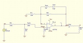
Hi Fabio, I see that you "overdid" a bit this whole impedance matching idea.
Let's try this:
1. remove RP1 and Rpot,
2. make Rpolw=100 - 500 R (5k6 is way, way to high - read the datasheet one more time)
3. Make Rpolpos = 100k (1K is very wrong value)
4. you need Rout only if you drive very long cables (high capacitance), but anyway Rout=10R is enough
Make these changes and tell us what you get
- Status
- This old topic is closed. If you want to reopen this topic, contact a moderator using the "Report Post" button.
- Home
- Amplifiers
- Chip Amps
- Nice Op Amp buffer for GC