great job..impressive
i've too recenlty made some boards for the little fella")
i've too recenlty made some boards for the little fella
An externally hosted image should be here but it was not working when we last tested it.
Hi,zatramusic
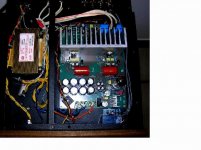
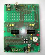
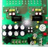
Hi,zatramusic, your PCB is so small. How about the voltage of your PCB?? Here are some pictures of my ECC88+LM1875 PCB,
being soldering now. I use 20V----0----20V AC , 150W transformer for power supply. The PCB is draw by protel.Including
the time delay part when power on.
Hi,zatramusic, your PCB is so small. How about the voltage of your PCB?? Here are some pictures of my ECC88+LM1875 PCB,
being soldering now. I use 20V----0----20V AC , 150W transformer for power supply. The PCB is draw by protel.Including
the time delay part when power on.
Attachments
hi Luck, i will use 2x18V 60VA per channel...
...the board is about 50x50mm and it's doublesided
..and they are made with eagle
your pcb's are far more complexed than mine..i wanted to stay minimal:
chip
8 diodes
3 resistors
2 capacitors
here's a picture
and another one
...the board is about 50x50mm and it's doublesided
..and they are made with eagle
your pcb's are far more complexed than mine..i wanted to stay minimal:
chip
8 diodes
3 resistors
2 capacitors
here's a picture
An externally hosted image should be here but it was not working when we last tested it.
and another one
An externally hosted image should be here but it was not working when we last tested it.
Hi,zatramusic
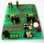
Hi,zatramusic, i can only see two resistors in your PCB,where is the left one? can you show me a picture including your transformer? it is suggest to put two caps with value 100nF close to LM1875.
Concerning my pcb ,it seems a little complexed. The IC that i use are : LM1875 for power output, LM7812 for the relay part, LM7806 for heating the lamp inside the tube.
Tomorrow i will finish all the soldering, then i will show you a picture....
Cheers...........
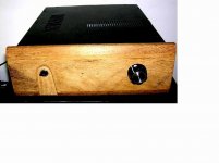
Hi Luck..
I've borowed my camera yesterday :/
The third resistror is on the other side of the pcb and the caps are 1000/50v...they are less then 20mm from the chip so it's ok
i used a toroidal transformer from http://www.toroidy.pl (a polish company)
bests
zatramusic
ps..as soon as i get my camera i will post some pics
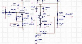
Hi Luck it looks better and better
I bought my trafos for about 10 euro piece
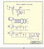
this is my schematic ( the 2.2uF input cap will be soldered directly from the board to the rca socket , and R3 is 680ohm)
and layout of the preamp i'm planning to do for it
bests
I bought my trafos for about 10 euro piece
this is my schematic ( the 2.2uF input cap will be soldered directly from the board to the rca socket , and R3 is 680ohm)
An externally hosted image should be here but it was not working when we last tested it.
and layout of the preamp i'm planning to do for it
An externally hosted image should be here but it was not working when we last tested it.
bests
Hi,zatramusic
You cancelled the e-cap that in the feedback circuit, how about the output offset of IC?? I made some test some weeks ago,
the output will be around 10MV,some will more than 15mV....
when power off, the LM1875 will bring a "pop" noise in your speak,isn't it ...... ...
it is suggest to put a R--C 10K----56P together with the feed back resitor R2 --22K..... the high frequence sounds will be a little smooth.
You cancelled the e-cap that in the feedback circuit, how about the output offset of IC?? I made some test some weeks ago,
the output will be around 10MV,some will more than 15mV....
when power off, the LM1875 will bring a "pop" noise in your speak,isn't it ......
...it is suggest to put a R--C 10K----56P together with the feed back resitor R2 --22K..... the high frequence sounds will be a little smooth.
haha..no, for start i will use opa134pa and than will see.. the preamp is universal and it's made using RJM's vsps phono preamp
as for the clicks and pops.. i've made an amp using this schematic for my friend and there is no pop's when turning on-off i would ommit the input cap too but i will use it with my sound card maya44usb which delivers huge dc when turning on-off... every chip is diferent and will deliver different output offset values ... as i remember the max acceptable dc is about 100mV
but if it will be necessary i'll include the zobel
see the original gaincard
HI.... zatramusic
I remember had made the sample just like the schematics you use with LM1875... i also cancelled the e-cap which should be around 10uf----47uf to make it work as a DC feedback circuit.
The output offset is below 10mV....At the beginning it works well,
but around two weeks later...two channalls have the noise at the same time......i checked it for a long time but can not find the reason,so i gave up at last.......
Then i make the new one with e-caps in feedback, as the pictures above............
- Status
- This old topic is closed. If you want to reopen this topic, contact a moderator using the "Report Post" button.
- Home
- Amplifiers
- Chip Amps
- My amplifier Using Tube buffer and LM1875