I have a ground loop but I'm having trouble working out how to get rid of it when I have so many grounds!
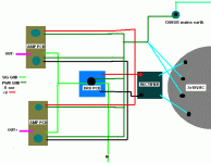
In my diagram, the power grounds and signal grounds join on the BrianGT amp PCBs and on the DRV134 PCBs. The other channel is a complete mirror of this one. I also joined power ground to the chassis other wise I get loud hum. My amp is dual mono in one case.
As it is now I get a quiet hiss (not silent) when no input is connected. If I connect one channel input to my preamp then that channel is silent and the other continues to hiss. If I connet both channel inputs to my preamp I get hum again. So I think the loop is between my power amp and preamp.
I've read the (many!) grounding threads but they only seem to cover simple GC grounding.
How do I get rid of this??
Is my ground loop caused by having (effectivly) 3x grounds (2x pwr, 1x signal) to my amp PCBs??
Any help much appreciated

Attachments
This should be quite easy to fix - your grounding is no good. Remove all the ground wires you have at present.
You should make the joint of the transformer secondaries your star ground. From here, take a wire off to each board ground and to the chassis earth.
Input and output sockets should be isolated from the chassis, if they are not already.
The DRV board appears to need a DC power input but you are feeding it straight off the bridge. Can you lash up a pair of caps before the board?
Should OG on the amp board be grounded, or is that simply where you connect the speaker return lead? (Look on the PCB to see if it's joined to PG).
I also believe the Brian boards should be fed with a dual rectifier bridge scheme (hence why there is PG+ and PG-) and you are using only one. So one part of the board is possibly not grounded.
No offence but have you actually read the instructions that came with the board from Brian?
richie00boy said:This should be quite easy to fix - your grounding is no good. Remove all the ground wires you have at present.
Good!
OKrichie00boy said:You should make the joint of the transformer secondaries your star ground. From here, take a wire off to each board ground and to the chassis earth.
Yep, they are.richie00boy said:Input and output sockets should be isolated from the chassis, if they are not already.
richie00boy said:The DRV board appears to need a DC power input but you are feeding it straight off the bridge. Can you lash up a pair of caps before the board?
This is a simplified diagram, there are 8x caps per rail after the rectifier and the DRV board have their own caps and then regs
OG and PG are joined on the PCB. All grounds join on the amp PCB.richie00boy said:Should OG on the amp board be grounded, or is that simply where you connect the speaker return lead? (Look on the PCB to see if it's joined to PG).
I don't think it makes any difference as all grounds join on the amp PCBrichie00boy said:I also believe the Brian boards should be fed with a dual rectifier bridge scheme (hence why there is PG+ and PG-) and you are using only one. So one part of the board is possibly not grounded.
richie00boy said:No offence but have you actually read the instructions that came with the board from Brian?
Of course, I've made a few GCs before but never had problems.
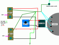
Thanks for your suggestions, I'll give them a go. I made a new diagram to represent what you said.
Attachments
Well its less but not gone 
If I move the position the input cable (which is shielded) around it changes from loud to quiet but still never completely gone.
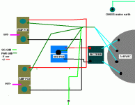
Here is how it looks now:
If I move the position the input cable (which is shielded) around it changes from loud to quiet but still never completely gone.
Here is how it looks now:
An externally hosted image should be here but it was not working when we last tested it.
Hi Brian,
can you rephrase that?
I am not sure I understand your US side wording.
Richie & Maxw,
I disagree on the location of the star ground (audio ground) and note the omission of the smoothing caps from the grounding scheme.
Can you clarify the PSU common and it's connection to the audio ground?
The centre tap connection direct to audio ground may be aggravating the hum.
can you rephrase that?
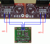
Here's a pic. No link between mains/chassis ground and audio ground.
Attachments
Hi Richie,
since my request was posted, I can see the photo and it shows a dual polarity smoothing bank of caps.
The centre tap must go to the smoothing cap common, not to the audio ground.
The smoothing cap common then gets a link to the audio ground.
Brain,
thanks for the diagram update.
Is this a case for a disconnecting network between the safety ground and audio ground?
Maxw,
you have connected the input ground to audio ground.
Would it be worth trying input ground to DRV ground first?
Can you understand the messages I have started this post with?
Superficially the different connection methods seem similar or even identical. But the voltages developed along even thick wires/plates can and do affect the input conditions of amplfiers.
Have you read any of my previous posts on grounding? I guess not, looking at your layout!
Is this a case for a disconnecting network between the safety ground and audio ground?
Yes. I fully expect to be heckled, but I also know it will eliminate the hum. Let the flaming begin...
Hi,
why do you expect to be heckled?
The safety ground does one job;-protect the user from electrocution.
The audio ground does a completely different job;-provides a clean voltage reference that all the other signal processing can use to allow accurate reproduction of the wanted input signal, excluding any noise added on it's route from source to input.
The two grounds do not need to be electrically connected, except in a few specialised situations and certainly do not benefit from a direct short, unless there is another fault built into the "system".
Phew. That's exactly right, but I have had the argument several times in the past, so I was ready to duck. Safety ground protects you if the chassis is somehow made "live."
In fact, in the US, it is usually tied to the mains neutral at the electrical panel. I don;t think anyone would think tying neutral to audio signal path would be a good idea.
In fact, in the US, it is usually tied to the mains neutral at the electrical panel. I don;t think anyone would think tying neutral to audio signal path would be a good idea.
As AndrewT stated earlier, i would try connecting your input-signal gnd ( shielded input-cable) to your driver-pcb first.
I can't give any detailed advice because i'm not familiar with the connections on the pcb's you're using.
Also your physical layout leaves somewhat to be desired.
FI your ac-mains-wiring running to your on/off switch should be kept as far away as possible from your amplifier-circuit, especially your input-wiring.
For general grounding-advice i refer to http://www.diyaudio.com/forums/showthread.php?s=&threadid=82880&perpage=10&highlight=&pagenumber=3
(post 21)
Everyone having problems understanding the concept of grounding should read this post and try to understand.
The only thing i can add to the post i refer to, is that you have to think of a wire not as a connection, but as a resistor.
With kind regards,
Klaas
Hi Kv,
thanks for the support.
Am I getter better at expaining this quite complicated process?
It's taken me years (no, decades) and finally this Forum to get to understand what I was doing wrong.
Another thread about teachers just got my attention. Same vein;- learning to make clearer explanations.
thanks for the support.
Am I getter better at expaining this quite complicated process?
It's taken me years (no, decades) and finally this Forum to get to understand what I was doing wrong.
Another thread about teachers just got my attention. Same vein;- learning to make clearer explanations.
Thanks everyone for the responses 
Yep, this is how I have it now and its much better.
The smoothing cap common is connected to star GND which is connected to audio GND on the amp PCBs.
Yep done this and its pretty good, the best I've had so far. I can only hear the amp when my ears are about 30cm from the speakers.
Yes! thanks.
Thanks, I'll try moving the switch to see if it makes a difference and that post gave a very good explaination.
If I have nothing connected to the input RCA its still quite loud, kind of a hiss. When my preamp is connected its very quiet but not silent like all my other GCs. I've tried connecting my input signal ground all over the place but no luck.
BrianDonegan said:Here's a pic. No link between mains/chassis ground and audio ground.
Yep, this is how I have it now and its much better.
AndrewT said:The smoothing cap common then gets a link to the audio ground.
The smoothing cap common is connected to star GND which is connected to audio GND on the amp PCBs.
AndrewT said:Maxw,
you have connected the input ground to audio ground.
Would it be worth trying input ground to DRV ground first?
Yep done this and its pretty good, the best I've had so far. I can only hear the amp when my ears are about 30cm from the speakers.
AndrewT said:Can you understand the messages I have started this post with?
Yes! thanks.
kvholio said:FI your ac-mains-wiring running to your on/off switch should be kept as far away as possible from your amplifier-circuit, especially your input-wiring.
For general grounding-advice i refer to http://www.diyaudio.com/forums/showthread.php?s=&threadid=82880&perpage=10&highlight=&pagenumber=3
(post 21)
Thanks, I'll try moving the switch to see if it makes a difference and that post gave a very good explaination.
If I have nothing connected to the input RCA its still quite loud, kind of a hiss. When my preamp is connected its very quiet but not silent like all my other GCs. I've tried connecting my input signal ground all over the place but no luck.
Hi,
you have confirmed this connection
I suggest you remove the smoothing cap common from the audio ground and remove the transformer centre tap from the audio ground.
Connect transformer centre tap to smoothing cap common.This figure of eight loop from transformer to rectifier to smoothing caps and all the way back to the transformer should be as compact as possible and all the wires in these loops should be as close together as possible to minimise "loop area".
Connect this new PSU common using a single wire link to the audio ground.
When you disconnect the input connector you are leaving the input unterminated. Some designs are specifically set up to tolerate this but others are not.
It sounds like your amp becomes noisy when the input is unterminated.
DO NOT power up your amp with the input unterminated. If you want to test the amp without the source connected then use a shorting plug on the unused input to force zero input signal conditions on the input of the amplifier.
you have confirmed this connection
but where does transformer centre tap connect to? I think you said it went to the audio ground.The smoothing cap common is connected to star GND which is connected to audio GND on the amp PCBs.
I suggest you remove the smoothing cap common from the audio ground and remove the transformer centre tap from the audio ground.
Connect transformer centre tap to smoothing cap common.This figure of eight loop from transformer to rectifier to smoothing caps and all the way back to the transformer should be as compact as possible and all the wires in these loops should be as close together as possible to minimise "loop area".
Connect this new PSU common using a single wire link to the audio ground.
When you disconnect the input connector you are leaving the input unterminated. Some designs are specifically set up to tolerate this but others are not.
It sounds like your amp becomes noisy when the input is unterminated.
DO NOT power up your amp with the input unterminated. If you want to test the amp without the source connected then use a shorting plug on the unused input to force zero input signal conditions on the input of the amplifier.
- Status
- This old topic is closed. If you want to reopen this topic, contact a moderator using the "Report Post" button.
- Home
- Amplifiers
- Chip Amps
- 2x LM4780 + DRV134 = hum Need grounding help!


