I named her MAHGER. If anyone knows how to go about getting a metal badge made........?
The down and dirty:
-The amp chassis is made of aromatic cedar.
-4 LM4780 chips each wired in parallel.
-Noble Pots. One controls the ESL's (highs). One controls the Woofers.
-2 420 VA torroids that are stacked and 1 12V transformer.
-4 Super Through caps 10,000uf.
-4 Gold Tune caps 4,700uf.
-Audioquest copperhead interconnect wire throughout.
The purpose of this amp is to power my Martin Logan Ascent i speakers in stereo mode. Essentially, this amp was disigned to bi-amp them. The 10,000uf channels push the woofers, while the 4,700uf channels push the electrostatic panels.
I know that I will probably receive some criticism for buying expensive interconnects and then cutting them up, but there really is a difference in sound (I did a side by side comparison). Will I ever do it again? ABSOLUTELY NOT. I spent about 300-400 on just the green wire (audioquest copperhead) you see in the pics, but there really is a difference in sound from my last LM4780 amp. I just think that it is getting into the "law of diminishing returns". None the less, I felt that I would try to run the exact same wire from the signal source to the speaker output. The difference can be described as the amp has taken a deep breath. The amp is more open, although not in an airy sense. Transients are lighter, but clearer.
I am very happy with this amp and it was an "all out" approach that I took in building it. A once in a lifetime thing although I will keep building.
Special thanks to other members: Peter Daniel, Lgreen, Poobah, Anatech, Bazukaz, Pinkmouse, Nuuk, Peranders, Sangram, Tiltedhalo, and to everyone that contributes to this site. DIY is just one generation away from dying and it is the passing of your knowledge that keeps it going.
Questions/Comments? I can take more pics if anyone has a specific request.
Dominick in New Jersey
Happy building
The down and dirty:
-The amp chassis is made of aromatic cedar.
-4 LM4780 chips each wired in parallel.
-Noble Pots. One controls the ESL's (highs). One controls the Woofers.
-2 420 VA torroids that are stacked and 1 12V transformer.
-4 Super Through caps 10,000uf.
-4 Gold Tune caps 4,700uf.
-Audioquest copperhead interconnect wire throughout.
The purpose of this amp is to power my Martin Logan Ascent i speakers in stereo mode. Essentially, this amp was disigned to bi-amp them. The 10,000uf channels push the woofers, while the 4,700uf channels push the electrostatic panels.
I know that I will probably receive some criticism for buying expensive interconnects and then cutting them up, but there really is a difference in sound (I did a side by side comparison). Will I ever do it again? ABSOLUTELY NOT. I spent about 300-400 on just the green wire (audioquest copperhead) you see in the pics, but there really is a difference in sound from my last LM4780 amp. I just think that it is getting into the "law of diminishing returns". None the less, I felt that I would try to run the exact same wire from the signal source to the speaker output. The difference can be described as the amp has taken a deep breath. The amp is more open, although not in an airy sense. Transients are lighter, but clearer.
I am very happy with this amp and it was an "all out" approach that I took in building it. A once in a lifetime thing although I will keep building.
Special thanks to other members: Peter Daniel, Lgreen, Poobah, Anatech, Bazukaz, Pinkmouse, Nuuk, Peranders, Sangram, Tiltedhalo, and to everyone that contributes to this site. DIY is just one generation away from dying and it is the passing of your knowledge that keeps it going.
An externally hosted image should be here but it was not working when we last tested it.
An externally hosted image should be here but it was not working when we last tested it.
An externally hosted image should be here but it was not working when we last tested it.
An externally hosted image should be here but it was not working when we last tested it.
An externally hosted image should be here but it was not working when we last tested it.
An externally hosted image should be here but it was not working when we last tested it.
Questions/Comments? I can take more pics if anyone has a specific request.
Dominick in New Jersey
Happy building
DIY is just one generation away from dying
A very sobering thought!

Have you tried the amp with your Martin Logans yet, and if so, how does it sound?
Nuuk,
yes, I have run the logans now for about 20 hours or so on this amp. Before the final build, I tried a series of combinations including cap changeouts and bi amp vs. bi wire.
I have to say that my biggest find was using the 10000uf superthroughs on the woofers. the bass was VERY noticably better. The same was not true for the esl panel. They like the smaller 4700uf cap better. My opinion of course. When using the larger cap, the midrange had sort of a low treble curtain placed over it. I did not like it at all and knew right away it would not do for the final design.
To me, bass is the hardest area to fine tune. It is really hard to notice differences, especially for those who are not into audio equipment. But this amp clearly outperformes my sony in clean, sharp, tight bass. Each note has a punctual beginning and end.
All in all, the headroon seems to be unlimited. I have not cranked it, but I have raised it to my maximum continuous listening level and it is everything I hoped it would be.
Also, SIBILANCE has virtually disappeared. Something I also attribute to the wires(in part). I think the signifcance in that goes without saying.
Thanks everyone.
Dominick
Looks like eastern red cedar (although a bit light for ERC) or redwood.
For getting a metal badge made, go to any trophy shop and they can make an engraved/silkscreen badge of any pattern made for you.
We just did that for a couple of custom plaques for some guys at work.
--
Danny
For getting a metal badge made, go to any trophy shop and they can make an engraved/silkscreen badge of any pattern made for you.
We just did that for a couple of custom plaques for some guys at work.
--
Danny
Wow! I really like the look of the thing and the blue lights. those wires inside remind me of "Alien." Really retro look. Congrats!
I am sure some will criticize your amp but as soon as I saw it I smiled, and then I read your description and smiled again.
Reminds me of, well.....you try and try to do the best you can and sometimes you spend a lot of money on some things that looking back you would not do again, and sometimes there are lots of wires going everywhere despite how you planned to make everything look neat....but as long as it works and you learn then there is value.
Remember that this is DIY and you made it like that because you wanted to... and that is all the reason you need.
Questions-
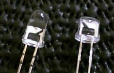
Did you ever consider getting some frosted glass /plastic for your little windows or do you like them clear like they are? I like the green wires, do they show well with the blue LEDs? Maybe tossing in a green or yellow in there will accentuate them more? You can never have enough bling")
Does the meter really show DC volts? which phase/ channel?
How about a top-down view? With the LM4780 people like to see the size of the heat sinks since these tend to get pretty hot, it would be neat to see how you are cooling everything.
EDIT- how hot do the sinks get?
EDIT#2- you can't just tell us a name...why did you pick it (unless it stands for something here and I missed it)
Is the cover done, what are you doing for that?
Looks good and keep making stuff, can't wait to see what comes next.
Did you see this thread? Might have to divide your 19.1 by 2.
I am sure some will criticize your amp but as soon as I saw it I smiled, and then I read your description and smiled again.
Reminds me of, well.....you try and try to do the best you can and sometimes you spend a lot of money on some things that looking back you would not do again, and sometimes there are lots of wires going everywhere despite how you planned to make everything look neat....but as long as it works and you learn then there is value.
Remember that this is DIY and you made it like that because you wanted to... and that is all the reason you need.
Questions-
Did you ever consider getting some frosted glass /plastic for your little windows or do you like them clear like they are? I like the green wires, do they show well with the blue LEDs? Maybe tossing in a green or yellow in there will accentuate them more? You can never have enough bling
Does the meter really show DC volts? which phase/ channel?
How about a top-down view? With the LM4780 people like to see the size of the heat sinks since these tend to get pretty hot, it would be neat to see how you are cooling everything.
EDIT- how hot do the sinks get?
EDIT#2- you can't just tell us a name...why did you pick it (unless it stands for something here and I missed it)
Is the cover done, what are you doing for that?
Looks good and keep making stuff, can't wait to see what comes next.
Dominick22 said:Quick question:
My torroids are each 420 VA with 22V rails. To get the current output, I would just divide 420 by 22-right?
Which is 19.1!
Is this the amount of current supplied on each rail? 19.1A
It seems a bit high?
Thanks,
Dominick
Did you see this thread? Might have to divide your 19.1 by 2.
An externally hosted image should be here but it was not working when we last tested it.
An externally hosted image should be here but it was not working when we last tested it.
An externally hosted image should be here but it was not working when we last tested it.
An externally hosted image should be here but it was not working when we last tested it.
An externally hosted image should be here but it was not working when we last tested it.
As far as the plastic is concerned, I like the idea of being able to see inside when it is off and I plan on making the cover with the same material to view from the top. They do show well although I would rate them an 8 or 9 based on my initial expectations. The windows are small enough that you cant tell too much, but there is a definite focus in the LED light beam that is hard to evenly disperse.
The wires as you can see in the above pis, were taken from actual interconnects, so the color scheme was decided by audioquest for that particular wire model. The exact same wire carries the signal from the cd player all the way to the speaker outputs.
The meter is mostly for looks I admit, but what it is reading is the voltage off of one Nichicon Super Through cap. It usually hovers around 1.8, so to get the actual reading (because of a resistor), you have to multiply 1.8 by 40.7. You end up around 73V which I tested and is accurate.
The heat sinks do get "very warm". They are not untouchable and there has never been an interruption in play (sometimes lasting 3 hours). They dissipate heat naturally and unassisted.
Mahger doesnt really stand for anything. Just a name I made up that I thought commanded respect. Doesn't it sound like the name of a gladiator?
The wood is from California, Eastern Red Cedat it may be?
LGREEN, thanks for the link, I did have to divided my A rating by 2. It is pushing 9.5A through each channel.
What do you think about 9.5A? Is this good? My ML's are very current hungry. Even the manufacturer states this.
Dominick
Dominick22 said:[BThe meter is mostly for looks I admit, but what it is reading is the voltage off of one Nichicon Super Through cap. It usually hovers around 1.8, so to get the actual reading (because of a resistor), you have to multiply 1.8 by 40.7. You end up around 73V which I tested and is accurate.
Dominick [/B]
good stuff. I hope that 73 V is across both rails, not rail-to-ground, and why is there a cap across the rails like this?
Dominick22
I can see on your pics that there is no smoothing caps on amp boards, I guess they were to big to place there.
Result is that current have a lower impedance path from rectifier to amp board than to caps resulting in some not decoupled diode switchnoise straight to amp.
Solution would be to remove power rail bridges between psu and amp. Solder wires from psu rails direct to respective cap and from there to amp board.
Finally 2 high quality caps on amp board for effective decoupling close to chip and ground return.
- Status
- This old topic is closed. If you want to reopen this topic, contact a moderator using the "Report Post" button.
- Home
- Amplifiers
- Chip Amps
- 2nd LM4780 BASED AMP COMPLETED-PICS*