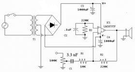
Yes, the input bias currents are flowing through the two balanced 220k resistors (the 10k on the inv input isn't there for DC) so unbalancing by deleting the one 220k will surely give gross DC output offset.
Cutting down the values on the 220k and 10k series R would be much better, also from a noise standpoint, but that would lower the Zin and you would need a lower vol control than 100k.
This is a major problem in inverting apps and also the reason why most would avoid it.
Jan Didden
Cutting down the values on the 220k and 10k series R would be much better, also from a noise standpoint, but that would lower the Zin and you would need a lower vol control than 100k.
This is a major problem in inverting apps and also the reason why most would avoid it.
Jan Didden
Thank you so much.
But I am very new here.
Can you Janneman can you explain in easier words?
I should keep 10K and reduce 220K to how many K?
Is this also reduce gain of my amp? [I am so confused. I am using OPA541AP chip, some said I should keep the gain at only 10, some said between 10 to 20 is ok. Do u have any idea?]
I only have 100K step, can I adjust it to 50K by parallel 100K resistor with the step output?
Nuuk said:Click on the www at the bottom of my posts.")
Hm, I can't see any URL there. But he can click on your name "Nuuk" instead, and find the link there.
Nuuk said:There is a button with www on it. In the same place there is a button with email on it at the bottom of your post!
Oh, sorry. I had never noticed it said "www" instead of "email" in your case.

Oh, sorry. I had never noticed it said "www" instead of "email" in your case.
No worries.
janneman said:Yes, the input bias currents are flowing through the two balanced 220k resistors (the 10k on the inv input isn't there for DC) so unbalancing by deleting the one 220k will surely give gross DC output offset.
Hi Jan,
I don't remember any of my IGC having "gross" DC output offset. (i.e. all were under 100mV, I think). DC output offset seems to vary quite a bit depending on the chip. If I was overly concerned, I'd recommend putting a pot in so DC output offset could be adjusted depending on chip variance.
Hi 5150ed,
My comments were regarding the LM3875 as per schematic, I have no experience with the OPA541AP chip.
As a matter of routine, you should always check DC output offset before connecting an amp to your speakers.
regards
I mean can I adjust 100K Pot to 50K by adding resistors, if yes how?
NO! If you are building an IGC then you really want a 10K pot anyway!
Have you read the FAQ at Decibel Dungeon? "The solution is to use a linear pot which has better tracking than it's equivalent log type. Then, we modify it to fake the curve that the log pot produces. The modification involves soldering a resistor between the out and ground pins of the pot, and this is called 'Law faking'. The value of the resistor used is between one tenth and one twentieth of the value of the pot. So, for a 100K pot the law faking resistor value is 5K and 10K, for a 50K pot 2K4 and 5K1, and for a 200K pot, 20K and 39K."
I quoted from your website, Nuuk.
Can that Law faking apply to the stepped attenuators as well?
Ho god I do not want to buy another real expensive stepped attenuators just because its impendence isn't match .
.
I quoted from your website, Nuuk.
Can that Law faking apply to the stepped attenuators as well?
Ho god I do not want to buy another real expensive stepped attenuators just because its impendence isn't match
.Can that Law faking apply to the stepped attenuators as well?
I don't think so but you mis-understand. Law-faking is not used to chaged the impedance of the pot.
What stepped-attenuator do you have there?
- Status
- This old topic is closed. If you want to reopen this topic, contact a moderator using the "Report Post" button.
- Home
- Amplifiers
- Chip Amps
- Inverted GainClone question?