i know that thread is realy old but i will try to parallel 5x lm317 and 5x lm337 with 0.22r on each lm output and to lm3875 stereo amp ... i have big trafo with more than enough current but recitified voltage is around 40v per rail so i must regulate and i have lots of theese lm regulators available so i will try
As Andrew says, start up could well be a problem. So could sudden short circuits. Also to get 0.22 ohm resistors to share the current well you'll probably need a preset pot on each of the regs to set the output voltages close enough together. 1% resistors won't get you close enough in practice where you're aiming for a high output voltage.
of course there will be pot to adjust them .. lot easier than matching resistors for me...
if lm-s are rated on 35v difference ,1.5A then everything i must take care of is not to put too big capacitor on lm outputs(amp input v) , in order not to blow them (lm317-s) on power up..is that correct?
if lm-s are rated on 35v difference ,1.5A then everything i must take care of is not to put too big capacitor on lm outputs(amp input v) , in order not to blow them (lm317-s) on power up..is that correct?
In many implementations you will see a diode to protect the 317/337 from reverse voltage after shutdown.
That diode can be replaced by a Zener to limit the IN/OUT differntial during startup and give reverse voltage protection.
The problem is that the Zener is power limited. If during start up the Zener is blowing then look at using a high power Zener, or using a transistor assisted Zener.
That diode can be replaced by a Zener to limit the IN/OUT differntial during startup and give reverse voltage protection.
The problem is that the Zener is power limited. If during start up the Zener is blowing then look at using a high power Zener, or using a transistor assisted Zener.
of course there will be pot to adjust them .. lot easier than matching resistors for me...
if lm-s are rated on 35v difference ,1.5A then everything i must take care of is not to put too big capacitor on lm outputs(amp input v) , in order not to blow them (lm317-s) on power up..is that correct?
Another easy way to violate the regulator's Vin-Vout max spec is to use "too much" capacitance when bypassing the adjust pin. Even 47 uF can very-easily do it, depending on reservoir C value. And 22uF or even 10 uF could do it.
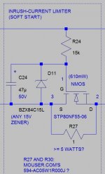
You could always use a soft-start circuit, between the rectifiers and the reservoir caps, something like the attached image, which was used in both 22V and 28V regulated supplies, for exactly that reason.
It works unaltered in both the positive and negative rails, without being flipped (i.e. the MOSFET is in the ground rail when the circuit is used for the positive rail and the MOSFET is in the -V rail when the circuit is used for the negative rail).
That circuit inserts a one-Ohm R into the power supply rail, only during startup, to limit the current, in order to slow down the startup (limits the rise time and overshoot of the reservoir caps' voltages so that the regulator's output voltage has time to keep up with the reservoir caps' voltage), and then gradually shorts that resistor with a large MOSFET, as the rail voltage comes up.
The one-Ohm resistor that I used was rated for 5 Watts but it never got even the slightest bit warm to the touch (since it's only in the circuit for a fraction of a second). So it probably could have a smaller power rating. (Maybe a different type could be used, too. That was the only one I found, that day, with a datasheet that showed for how long the extremely-large start-up charging inrush currents could be tolerated by the resistor.)
Attachments
Last edited:
TI has the 5-Amp adjustable LM1084, available at Mouser.com for $2.43 for quantity 1:
LDO Voltage Regulators | Mouser
http://www.ti.com/lit/ds/symlink/lm1084.pdf
It looks like the input-output max is 29 V, for that one.
But TI's 5-Amp adjustable LM338 is only $2.03, for quantity 1:
Voltage Regulators - Standard | Mouser
http://www.mouser.com/ds/2/282/snvs771a-123143.pdf
And it does state a max +40V/-0.3V I/O differential.
An externally hosted image should be here but it was not working when we last tested it.
i will try with 5 of theese but it looks like this are the fake ones 337 on left
Just a few ideas to throw into the pot here - not sure if they were mentioned in the older part of the thread.
5x317s seems a bad idea to me. If you must use a 317 then there are plenty of regimes for putting a power transistor outside it. This will improve regulation - cos more gain. A 3055 or TIP35C would be ideal here. Find Linsley Hood's power supply to see one way this can be done.
338s are jolly good things and I have used them to good effect in v similar circumstances. If you are worried about heat or max current, use one on each channel and get the benefit of that as well. There are plenty of schematics for getting V-, if you need it.
There is no problem with 40V input V. I have used over 50V without any problem, but with, at the v least, a discharge diode for when you switch off.
A 12V drop across a 317, or 318 is not at its limit (which is probably about 17 or 18V in this sort of use) but it's not ideal. It HAS to be dissipated so your 317 will get too hot; and there are no benefits in regulation beyond about 5 or 6V dropout.
Use a zener on the Adj pin. This allows you much more feedback and therefore much better regulation.
Do not go overboard on the output cap of the 317 (less than 10u at a guess) and have it be lossy - or put a series R in with it. And take into account whatever Cs you have hanging around op amps as well.
Hope this helps.
i wanted to do without transistor not shure wy but i tryed ...
338 are 20 bucks in my country so that wasnt my goal ..better buy new trafo
this 337 i have, have proved to be fault
looks like i will use some old tda7294 amp that could survive this voltages with 8r speaker
i will use 317 in preamps and filters cos i have not centre tapped trafos for that so i can use them ..
for amp i think i will use that linsley hood regulator with 2n3055 an mj2955 cos that are cheap and easy to get in my country altough not motorola ones
thanks on help!
- Status
- This old topic is closed. If you want to reopen this topic, contact a moderator using the "Report Post" button.
- Home
- Amplifiers
- Chip Amps
- Regulated PS w/ LM317 & LM337's