Try the Chipamp forum @ diyaudio.com 
You could start with the reference design in the spec sheet to get your feet wet. Decibel Dungeon also has a lot of info together.
You could start with the reference design in the spec sheet to get your feet wet. Decibel Dungeon also has a lot of info together.
davidlzimmer said:PS. I also did not use Cm or switch. Just wired Rm striaght to V-.
Hi,
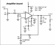
I would like to ask , what is purpose of R1, R2 in the circuit ? Seems of no use to me.
Regards,
Lukas.
Disclaimer: I don't know. Hopefully the more knowledgeable will jump in.
As far as R1, I was curious myself. While bench testing, I temporally bypassed R1 and noticed no difference.
R2 is in every chimpamp circuit. I've always assumed it set up a reference voltage like bias.
As far as R1, I was curious myself. While bench testing, I temporally bypassed R1 and noticed no difference.
R2 is in every chimpamp circuit. I've always assumed it set up a reference voltage like bias.
Coupling/input caps aren't necessiary for these circuits in my experience. If you want to add one in, be sure to make it pretty high quality since it can make a substantial impact on the sound of the amp.
It makes sense to me that R1 and R2 are there to set up an input voltage divider. R1+Rin makes the first stage, but on looking at it again, it is a little wierd. . .
It makes sense to me that R1 and R2 are there to set up an input voltage divider. R1+Rin makes the first stage, but on looking at it again, it is a little wierd. . .
Oh yea, back on topic, in addition to the gainclone-esque circuits, I like the Linkwitz LM3886 implementation(attached). I am powering mine with +/-30V rails with 4,400uf per rail using a dual mono unregulated PSU. This is probably a little overkill, and the amps definitely work with 2,200uf/rail/chip, but I had a surplus of 2,200uf caps laying around, and one thing led to another. . .
Attachments
Determination of whether the input coupling (DC blocking) cap is needed depends on the DC offset (or lack thereof) from the prior stage.
Prior stage is commonly the source, or a buffer/pre/etc. Many have coupling caps on their outputs already, in which case another coupling cap on the power amp stage input is redundant. Some (especially DIY), "might" not have that output coupler cap, so before one goes amplifying the signal to power amp levels it is important to measure for the DC offset (L to Gnd, and R to Gnd) if there is any uncertainty.
Prior stage is commonly the source, or a buffer/pre/etc. Many have coupling caps on their outputs already, in which case another coupling cap on the power amp stage input is redundant. Some (especially DIY), "might" not have that output coupler cap, so before one goes amplifying the signal to power amp levels it is important to measure for the DC offset (L to Gnd, and R to Gnd) if there is any uncertainty.
The circuit shown is with the variable pot for volume control. The way the circuit is usually shown (the base model) is without the pot.
I believe that without the pot, resistors R1 and R2 would be needed, the pot does seem to make them superfluous.
That's why they show up in this circuit though, it's the original circuit with a pot slapped on the input stage.
I believe that without the pot, resistors R1 and R2 would be needed, the pot does seem to make them superfluous.
That's why they show up in this circuit though, it's the original circuit with a pot slapped on the input stage.
- Status
- This old topic is closed. If you want to reopen this topic, contact a moderator using the "Report Post" button.
- Home
- Amplifiers
- Chip Amps
- Lm3886t