Carlp,Pjotter,
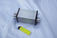
Well, that puts my little project to shame! Incredible. Solid block of aluminum milled? That's WAY beyond my audio budget. But maybe you have connections... Anyway, very nice work. But what about the L channel of input 1? And what of those RCAs sticking out of the bottom? And what chip are you using?
It didn't put your project to a shame, it's just different
") where's your project located? I'd love to see it.
where's your project located? I'd love to see it.It is a solid block of aluminum. I'm a cnc machinist so that's why I'm able to make it like this.
You can click on the link in the top of the post, the whole project is there.
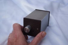
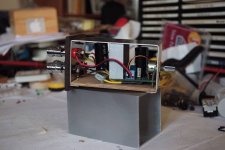
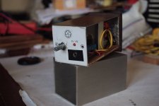
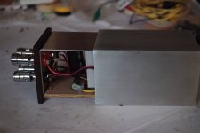
There's a small bracket inside which is in front of the hole for the rca, I'll have to adjust the bracket in order to make it fit.
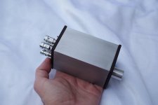
The rca you see at the bottom are temporary soldered to the pcb so I could test everything before I actually milled the aluminum.
I'm using the lm3886 chips ;-)
More information is found in my project thread, if you like you can follow the build there because she isn't finished yet
Last edited:
Well, you're right, they ARE different. Among other things I'm someone who likes to re-use and repurpose, so mine is partly a scrap bin project. But I do love the solid aluminum approach. You've done impressive work. Thanks for the details on the project. I did eventually take a look at your thread but hadn't seen any mention of the LM3886 and didn't read about the bottom RCAs. It all makes more sense now.
My project post:
http://www.diyaudio.com/forums/chip-amps/79303-chip-amp-photo-gallery-275.html#post4055450
My project post:
http://www.diyaudio.com/forums/chip-amps/79303-chip-amp-photo-gallery-275.html#post4055450
Small is beautiful
Here's a very small chip amp (TDA7297 ebay module), which I finally managed to finish. I've had this idea for some time, but the build was rather complicated, given my lack of "proper" tools. Everything was done by hand, no CNC machinery in my garage
Rather small compared to other builds in this thread, but still interesting. I think it looks OK
Attachments
Very very nice!Here's a very small chip amp (TDA7297 ebay module), which I finally managed to finish. I've had this idea for some time, but the build was rather complicated, given my lack of "proper" tools. Everything was done by hand, no CNC machinery in my garage
Rather small compared to other builds in this thread, but still interesting. I think it looks OK
You happen to have some pictures of the inside? I'm curious to the heatsink
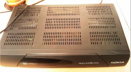
Sanyo + nokia peace, friendship
Nice re-purposing, vdij! What does it sound like? I have two STK chips (I don't think they're 4048 but can't recall what) from an old receiver and have wondered if they're worth tinkering with.
Here's a very small chip amp (TDA7297 ebay module), which I finally managed to finish. I've had this idea for some time, but the build was rather complicated, given my lack of "proper" tools. Everything was done by hand, no CNC machinery in my garage
Rather small compared to other builds in this thread, but still interesting. I think it looks OK
Nice work, den_hr. That's impossibly small! I too wonder about heat sinks or dissipation.
Very very nice!
You happen to have some pictures of the inside? I'm curious to the heatsink
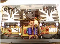
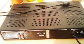
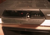
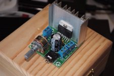
Here are a few pics of the inside. I'm running it on 12V, and the heatsink doesn't really get warm - we'll see how it behaves inside. But, the heatsink touches the inside aluminium "sled", so that might help a little. No heat paste or anything - but the chip doesn't get really hot on 12V, so I think it's OK.
The first image is the photo of the ebay kit, as purchased - I've done some mods on it, so it's not stock...
The other pics show the insides... Relatively messy, but I think it will be OK...
Attachments
Last edited:
Really nice, den_hrHere are a few pics of the inside. I'm running it on 12V, and the heatsink doesn't really get warm - we'll see how it behaves inside. But, the heatsink touches the inside aluminium "sled", so that might help a little. No heat paste or anything - but the chip doesn't get really hot on 12V, so I think it's OK.
The first image is the photo of the ebay kit, as purchased - I've done some mods on it, so it's not stock...
The other pics show the insides... Relatively messy, but I think it will be OK...
I'm not sure about this chip, but if I'm not mistaken for the lm3886 you're supposed to use an insulation pad between the chip and heat sink if you're using the uninsulated chip (tf addon after the lm3886).
But again, I really like this amp. You've done a great job.
This is why I like opamps so much, you've just used a few square cm to build an amp while other amps can be a lot bigger and heavier with a load of power (Jeff Rowland concentra ii for example)
Kudos to you, really like it. Made my day!
Really nice, den_hr
I'm not sure about this chip, but if I'm not mistaken for the lm3886 you're supposed to use an insulation pad between the chip and heat sink if you're using the uninsulated chip (tf addon after the lm3886).
Thanks for the compliments - nice to see one's work appreciated
Even more so since it was done using really primitive tools (no drill press, no CNC machinery....)
As for heat dissipation, it shouldn't really be much of a problem - like I said, I've used it (albeit "open", without the case) on 12V, and the heatsink gets mildly warm...
More about this amp here: "What the heck? It's less than lunch!".
I assume that's 12v and a max of 1.25 amps minimum (at 15wpc output) which means this isn't really for battery power. Or is it? How are you powering this? Wall-wart? Separate PS? SLA battery?
Note it's NOT the insulated LM3886 (metal tab in the photo), so you should insulate between the chip and the heat sink if you haven't.
Note it's NOT the insulated LM3886 (metal tab in the photo), so you should insulate between the chip and the heat sink if you haven't.
Ahhh, egg on my face!
Sorry, I didn't see that for some reason. I can't tell from the data sheet if the tab is connected (usually to ground) but it doesn't SEEM to be. Data sheet also doesn't claim to be high performance or anything like that, so now I'm REALLY curious how it sounds. Supply can be 6-18v, so wondering too how 12v sounds. At $5 shipped, that's quite an inexpensive amp!
Sorry, I didn't see that for some reason. I can't tell from the data sheet if the tab is connected (usually to ground) but it doesn't SEEM to be. Data sheet also doesn't claim to be high performance or anything like that, so now I'm REALLY curious how it sounds. Supply can be 6-18v, so wondering too how 12v sounds. At $5 shipped, that's quite an inexpensive amp!
... but the chip doesn't get really hot on 12V, so I think it's OK. ... The first image is the photo of the ebay kit, as purchased ... The other pics show the insides... Relatively messy, but I think it will be OK...
Plywood is a misunderstood building material. ...
Really nice job ...
Thank you. Great sound, you can build an amplifier.Nice re-purposing, vdij! What does it sound like? .
Hi,
Just finish..
LM3875, kit from LJM.
Phil.
Just finish..
LM3875, kit from LJM.
An externally hosted image should be here but it was not working when we last tested it.
An externally hosted image should be here but it was not working when we last tested it.
An externally hosted image should be here but it was not working when we last tested it.
An externally hosted image should be here but it was not working when we last tested it.
Phil.
Hi,
Just finish..
LM3875, kit from LJM.
Phil.
Very, Very nice Phil!
I really like your power cord, any info on that?
Overall impression? GREAT! very neat.
Also nice internal wiring, like the twisted wires to your speaker binding posts.
- Home
- Amplifiers
- Chip Amps
- Chip Amp Photo Gallery