Post some then!
As Andrew T would no doubt say, safety first - second and last.
No idea what kind of footwear he favours Bob, but if I had to guess, I'd say safety boots
There,

Where is yours?
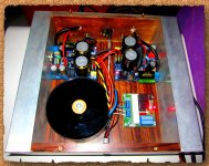
And yes, it is AGAIN a LME49811 and so on...
I am not going to answer any questions because of the contract reasons, so DO NOT ASK!
This design was sold.
Nice looking amp, but if it's not DIY project oriented I don't understand the purpose of posting the photo. I say that not to be small minded, but it appears to be an interesting combination of through hole and SMD technologies.
Maybe you could post a non-commercial version and let us have at it. Looks like it could be fun to build and produce high quality stable sound.
Congrats on the sale. That's a dream scenario/result for most of us in this DIY community.
Maybe you could post a non-commercial version and let us have at it. Looks like it could be fun to build and produce high quality stable sound.
Congrats on the sale. That's a dream scenario/result for most of us in this DIY community.
Last edited:
Closest match is this:
http://www.diyaudio.com/forums/solid-state/244746-testboard-lme49830.html
Although with the sister chip...
Untested board.
Discussion of similar implementations / suggestions of improvements in there please.
http://www.diyaudio.com/forums/solid-state/244746-testboard-lme49830.html
Although with the sister chip...
Untested board.
Discussion of similar implementations / suggestions of improvements in there please.

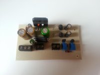
I can't find CL60 here, while the softstart kit is so cheap $3 only, I like the design of utilizing 2 relays, I think it's for safety in case 1 relay is failed. I changed the relay to omron and elco to pan fc, others seem good. I count it gives start up delay around 2sec
Picture should be able to tell more than I can explain
ahh..just find out that I have not cleaned the pencil marking yet on heatsink
Picture should be able to tell more than I can explain
ahh..just find out that I have not cleaned the pencil marking yet on heatsink
Attachments
Last edited:
I can't find CL60 here, while the softstart kit is so cheap $3 only, I like the design of utilizing 2 relays, I think it's for safety in case 1 relay is failed. I changed the relay to omron and elco to pan fc, others seem good. I count it gives start up delay around 2sec
Picture should be able to tell more than I can explain
ahh..just find out that I have not cleaned the pencil marking yet on heatsink
Softstart circuits usually have 2 relays. One of them turns the whole thing ON connecting the load through NTC resistors, and after a short while (2-5 sec) the second relay bypasses them for a straight path.


Ok, I'll post some pics
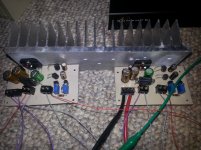
I just finished a set of LM3886 amps. Not in a chassis yet.
They use LDRs as Ri and Rb at 1k and 680R. Input resistor to ground is a 22k Spicer wirewound.
Non-inverting.
Rf is a Vishay S102 at 20k. Caps are Nichicon FG and FW.
I fitted the delay circuit with the Zener at 14V and a 6k8 resistor from negative to mute pin.
Zobel is made of 4x higher value resistors. If there was any inductance in the resistors its now down by a lot. .1uf zobel cap is underneath and is just a good quality Epcos. I had one of those russian K73 or K75, forget which, but this sounds better.
LDRs are driven by LM334 and they get their regulated voltage via a 3k resistor to a 6v8 zener. LDRs have a small electrolytic and .1uf ceramic in parallel with their LED side.
I have to say I was completely blown away from the first few notes. This is the best sounding LM3886 I've built to date. I wish I could compare with my old MyREF but I sold it. I dont remember being this stunned by the MyREF though.
Attachments
Thanks Troy!
They will be even better if I can track down the cause of that hum issue.
Hum issue tracked down, it's not the amp's or DCB1.
My passive pre has developed a fault
I just finished a set of LM3886 amps. Not in a chassis yet.
They use LDRs as Ri and Rb at 1k and 680R. Input resistor to ground is a 22k Spicer wirewound.
Non-inverting.
Rf is a Vishay S102 at 20k. Caps are Nichicon FG and FW.
I fitted the delay circuit with the Zener at 14V and a 6k8 resistor from negative to mute pin.
Zobel is made of 4x higher value resistors. If there was any inductance in the resistors its now down by a lot. .1uf zobel cap is underneath and is just a good quality Epcos. I had one of those russian K73 or K75, forget which, but this sounds better.
LDRs are driven by LM334 and they get their regulated voltage via a 3k resistor to a 6v8 zener. LDRs have a small electrolytic and .1uf ceramic in parallel with their LED side.
I have to say I was completely blown away from the first few notes. This is the best sounding LM3886 I've built to date. I wish I could compare with my old MyREF but I sold it. I dont remember being this stunned by the MyREF though.
Nice work U!
I love the sound quality from the couple of LM6883 amps I have heard so far, it's a great chip IMO.
Even better that you came up with your own version and boards to your own spec.
Thanks DavyM
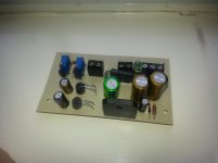
The Rf resistor and the 22k Spicer were both fitted directly to the LM3886 pins. Here is the board layout.
RM=6k8
Zm=14V .5W zener
Cm=47uf Nichicon FW 35V
C1, C2=220uf Nichicon FG 35V
RZ= ~8R and Cz=.1uf.
Cf=100uf 35V BP Nichicon Muse
P1 and P2 =2k trimmers
CS1 and CS2= LM334
R1=3k .25W
Z1=6v8 .5W zener
C3 and C4=100uf Nichicon FW 25V
C5 and C6=.1uf 50V ceramic cap
LDR1 and LDR2=NSL32SR2
There is a Link because you power the LDRs by themselves first, dial them in, then solder the link and power up the whole board. This way you dont have Ri and Rb at millions of ohms with the amp powered up.
Attachments
Last edited:
That looks like a nice layout, good on you!
I'm starting to wish I hadn't bothered with the My Ref's now, the only things I can connect to them and not get hum issues is either a shorted phono plug or an ipod.
This diy lark can be a pain in the butt at times eh.
Have you tried the amp with pgnd connected?
My DCB1 has no controls fitted to it, I am controlling source selection and volume with a small passive unit I made some time ago. Sources plug into that passive unit which is connected to the DCB1 by a short interconnect. The DCB1 then feeds the power amp's. This arrangement worked fine with my previous chip amp.
Even with my DAC plugged straight into the FE's and using my PC which feeds it to control volume I still get a loud hum.
I'll have a go at the FE's later on to see if I can get them to work better.
Davy
Even with my DAC plugged straight into the FE's and using my PC which feeds it to control volume I still get a loud hum.
I'll have a go at the FE's later on to see if I can get them to work better.
Davy
- Home
- Amplifiers
- Chip Amps
- Chip Amp Photo Gallery