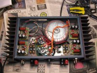
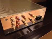
3886 Quad power amp
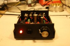
I built this last year and am very happy with it. I just wish I'd built two of them, so I could have the 7 channels I need for my stereo holographic soundbar project that I'm doing now. Sorry no front shot. The front has a power switch, a power on LED, and a window with the four peak level indicators (7 LEDs per channel) behind it. 65 watts into 8 ohms is generally enough for me, although I do use Hafler DH220's (125 watts/ch.) on the woofers which are active EQ'd to be acoustically flat at the couch to 20HZ).
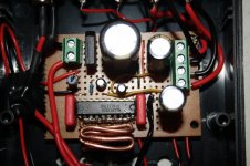
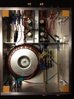
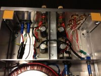
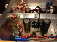
Oops, this shot is not the one I thought it was... Here it is half built anyway.
I built this last year and am very happy with it. I just wish I'd built two of them, so I could have the 7 channels I need for my stereo holographic soundbar project that I'm doing now. Sorry no front shot. The front has a power switch, a power on LED, and a window with the four peak level indicators (7 LEDs per channel) behind it. 65 watts into 8 ohms is generally enough for me, although I do use Hafler DH220's (125 watts/ch.) on the woofers which are active EQ'd to be acoustically flat at the couch to 20HZ).
Oops, this shot is not the one I thought it was... Here it is half built anyway.
Attachments
Nice job! Where did the enclosure come from? I've been looking for some nice two part extruded enclosures, without much luck.
small garage/workshop amp (for mobile phone, mp3 player etc) from salvaged and used parts only: TDA 2005M in BLT mode with high gain from datasheet circuit ; p2p; any AUX PSU 9-18V
tnx, tray this link (there are many different sizes of these "project Boxes":
diy project box in Business & Industrial | eBay
diy project box in Business & Industrial | eBay
TPA1517 amp
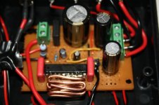
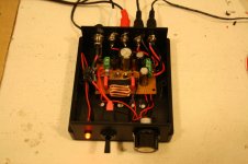
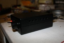
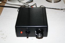
Here are some photos of my first chip amp, which I completed yesterday. It's a cheap and cheerful TPA1517 amp, powered from a 12VAC wall wart. I am using it with some cheap bookshelf speakers I picked up from a thrift store for $7.50. Obviously neither the amp nor speakers are hi fi, but they actually sound quite good to my ears, especially when you consider the overall price of the system. Certainly a huge step up from laptop speakers!
Nothing too pretty or interesting to look at, except perhaps for my improvised heatsink. Pins 10-20 of the TPA1517 (i.e. one whole row of the chip) are heatsink pins. The idea is that if you are etching a PCB for this chip you connect these pins to a big copper plane to act as a heatsink. Since I was using protoboard and not my own PCB, this wasn't an option for me. So I took some heavy guage copper wire, like what they use for house wiring, and bent it into an elaborate little miniature radiator shape, and soldered part of it all along the relevant side of the chip, as you can see in the photos. There's also some more of that wire on the underside of the board. This system seems to be working well enough. The chip doesn't get that hot in the first place.
I highly recommend the TPA1517 as a very simple project for beginners. It runs from a single-sided supply, requires the bare minimum of external components, has the gain internally set to a sensible level (20db) and puts out more than enough power for sensitive speakers (6W per channel into 4 ohm), and sounds pretty good. Should be far more rewarding than two LM386 chips for about the same complexity.
Attachments
Thanks, pinkugkc.
AudioSan, yes, the 6W is peak, obviously continuous power is much lower. But with sensitive speakers 1.5W is more than loud enough for domestic listening. I don't think I'd ever turn the volume on this past the half way point, since I live in an apartment building and have neighbours to be considerate of.
AudioSan, yes, the 6W is peak, obviously continuous power is much lower. But with sensitive speakers 1.5W is more than loud enough for domestic listening. I don't think I'd ever turn the volume on this past the half way point, since I live in an apartment building and have neighbours to be considerate of.
LM3886 Stereo Amp DIY
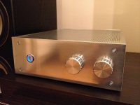
My recent project. Using a pair of LM3886 amp chip from National Semiconductor. The reference circuit is simple enough. I built two and put them in a compact case.
Single channel:
Stereo:
Put together:
Case closed:
Playing with my modified X-10D:
My recent project. Using a pair of LM3886 amp chip from National Semiconductor. The reference circuit is simple enough. I built two and put them in a compact case.
Single channel:
An externally hosted image should be here but it was not working when we last tested it.
Stereo:
An externally hosted image should be here but it was not working when we last tested it.
Put together:
An externally hosted image should be here but it was not working when we last tested it.
Case closed:
An externally hosted image should be here but it was not working when we last tested it.
Playing with my modified X-10D:
An externally hosted image should be here but it was not working when we last tested it.

- Home
- Amplifiers
- Chip Amps
- Chip Amp Photo Gallery