Like it alot
Interesting enclosures and extremely well made! It must of taken you a while to design them and fabricate them, are u by chance a machinist?
They have a certain simplicity or minimalistic character. Sort of reminds of some mark levinson equipment.
Anyways, very, very impressive.
Interesting enclosures and extremely well made! It must of taken you a while to design them and fabricate them, are u by chance a machinist?
They have a certain simplicity or minimalistic character. Sort of reminds of some mark levinson equipment.
Anyways, very, very impressive.
The P06 sounds good! A little light on the low end but I just threw it together from spare parts. I used a TL084. I plan on another with high quality parts. It still is very close to my 12ax7 tube preamp. Open and airy. Smooth mids.
The P06 needs to be driven into a buffer. I have a TL084 buffer before the 10k pot in the amp. I have found it also helps the CD players sound greatly. I think a buffer is mandatory for a gainclone. I've got to order some other opamps and compare.
Update: I finally got back to this amp. I found I had a 220 nF instead of a 22nF on the P06 preamp. It sounds MUCH better now. Full bass. It sounds fantastic!! I am using OPA2134 chips.
Interesting enclosures and extremely well made! It must of taken you a while to design them and fabricate them, are u by chance a machinist?
They have a certain simplicity or minimalistic character. Sort of reminds of some mark levinson equipment.
Anyways, very, very impressive.
Thanks Chris
") .
.The enclosures took a while to finish. My primary occupation is quite the opposite of a machinist
..I work with software, I do work on motorcycles sometimes..2.1 self-powered set
Besides a small amp using a lm4780, this is my first big and super-involved project. It's been done for about a month, and I am really happy with the results.
It's a 2.1 set of self-powered speakers. I'm using Hivi drivers (m8n, b4n, tn25)
All active circuits are in the subwoofer very similar to a plate amp.
There is a bridged lm4780 powering the sub (which is more than enough)
a lm4766 powers the satellite speakers
antek toroid, nichon caps, and custom pcbs-using parts-express' presensitized double-sided pcbs.
There is a 2nd order linkwitz-riley passive crossover in each satellite
Cables are custom made, speaker cables are 14 gauge stranded pure copper with rca on each end (because I could)
I made the cabinets from .75" red oak
Back panels were made at cometic gaskets, they are cnc cut with a water jet. .08" aluminum, I sent them my drawings and got it back, perfectly cut out.
Heatsink is from heatsink usa, went with their custom machining service.

here's the finished set

.75" Red Oak

Back of the bookshelf speakers, what the metal panels will mount onto.

test fit of hivi b4n & tn25

finished satellite, bolts are 18-8 (ss) socket cap #8-32 hex bolts from boltdepot.com.

unfinished sub

back of them finished
Controls are as follows:
top knob: subwoofer volume, have gain set so that middle is 0dB, it is a switching potentiometer. When clicked "off" the lm4780 is muted, and the low-cut is taken off of the satellite speakers. When the sub is clicked on the lm4780 is unmuted, and the low frequencies are cut from the satellites (crossover is at 150Hz, might change it to 100 in the future). If you'd rather not have the low frequencies be cut from the satellites depending on the switch in the potentiometer you just press the button next to the knob, it cancels this feature.
2nd knob: bass eq, center detent for 0dB change, this is an overall eq, so is effective before the active crossover. This means if you have the subwoofer clicked off and want a little more bass to the satellites you can use this knob for that too
3.5mm input, rca input
R + L speaker outputs
main power, fuse, IEC

another shot

when main power (switch in back) is turned on, the volume potentiometer at the front of the sub is a switching potentiometer, so turned fully down clicks off, and the set is in standby, led is red

when the potentiometer is turned up the set turns on, led is light blue, (not shown, when sub is "clicked" off led is dark blue. Led and potentiometer are both mounted on a small piece of metal, same material that the back panels are made from.

looking into the sub with the speaker removed

Power amplifier board

Active filter board

back panel, from left, power amp board, psu, and active filter. foam is to stop wires from rattling.
Welp, that's everything. Just wanted to share, I learned a great deal from this site, and these took me ~4.5 months and cost 600-700 usd. I'd answer any questions too.
Besides a small amp using a lm4780, this is my first big and super-involved project. It's been done for about a month, and I am really happy with the results.
It's a 2.1 set of self-powered speakers. I'm using Hivi drivers (m8n, b4n, tn25)
All active circuits are in the subwoofer very similar to a plate amp.
There is a bridged lm4780 powering the sub (which is more than enough)
a lm4766 powers the satellite speakers
antek toroid, nichon caps, and custom pcbs-using parts-express' presensitized double-sided pcbs.
There is a 2nd order linkwitz-riley passive crossover in each satellite
Cables are custom made, speaker cables are 14 gauge stranded pure copper with rca on each end (because I could)
I made the cabinets from .75" red oak
Back panels were made at cometic gaskets, they are cnc cut with a water jet. .08" aluminum, I sent them my drawings and got it back, perfectly cut out.
Heatsink is from heatsink usa, went with their custom machining service.
here's the finished set
.75" Red Oak
Back of the bookshelf speakers, what the metal panels will mount onto.
test fit of hivi b4n & tn25
finished satellite, bolts are 18-8 (ss) socket cap #8-32 hex bolts from boltdepot.com.
unfinished sub
back of them finished
An externally hosted image should be here but it was not working when we last tested it.
Controls are as follows:
top knob: subwoofer volume, have gain set so that middle is 0dB, it is a switching potentiometer. When clicked "off" the lm4780 is muted, and the low-cut is taken off of the satellite speakers. When the sub is clicked on the lm4780 is unmuted, and the low frequencies are cut from the satellites (crossover is at 150Hz, might change it to 100 in the future). If you'd rather not have the low frequencies be cut from the satellites depending on the switch in the potentiometer you just press the button next to the knob, it cancels this feature.
2nd knob: bass eq, center detent for 0dB change, this is an overall eq, so is effective before the active crossover. This means if you have the subwoofer clicked off and want a little more bass to the satellites you can use this knob for that too
3.5mm input, rca input
R + L speaker outputs
main power, fuse, IEC
another shot
when main power (switch in back) is turned on, the volume potentiometer at the front of the sub is a switching potentiometer, so turned fully down clicks off, and the set is in standby, led is red
when the potentiometer is turned up the set turns on, led is light blue, (not shown, when sub is "clicked" off led is dark blue. Led and potentiometer are both mounted on a small piece of metal, same material that the back panels are made from.
looking into the sub with the speaker removed
Power amplifier board
Active filter board
back panel, from left, power amp board, psu, and active filter. foam is to stop wires from rattling.
Welp, that's everything. Just wanted to share, I learned a great deal from this site, and these took me ~4.5 months and cost 600-700 usd. I'd answer any questions too.
twisted pairs.....twisted pairs......twisted pairs
I was waiting for you to say that. Had you on a timer
I was waiting for you to say that. Had you on a timer
We should have placed bets.

twisted pairs.....twisted pairs......twisted pairs
His project looks fantastic and that all you have to offer? LOL
Stereo Amp for PC Speakers.
Just made a stereo amp for my PC Speakers. Cabinet yet to be covered with brushed aluminum sheet & machined right side plate. Running on 15-0-15, 3A transformer.
http://postimage.org/gallery/2r79wcgw/


Just made a stereo amp for my PC Speakers. Cabinet yet to be covered with brushed aluminum sheet & machined right side plate. Running on 15-0-15, 3A transformer.
http://postimage.org/gallery/2r79wcgw/
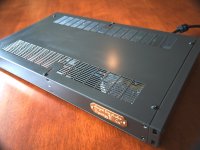
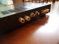
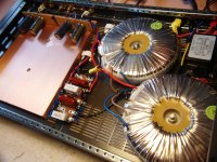
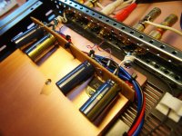
SynergyII\Cu started with 3.6kg of 100% very thick copper plate. The enclosure was selected, a 1U, 19” rack mount. The challenge was to build a pure Gainclone with its three resistors and simple 1500uf storage caps in a compact 1U enclosure. Everything had to fit in this tiny space including 48VAC of tranni, power filters and rectifier cct. Amp weighs 9.6kg.
Attachments
Last edited:
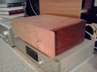
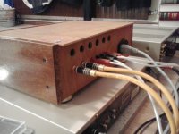
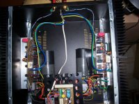
I'm old school
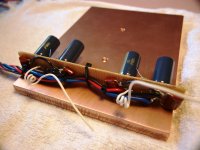
Just a bunch of wood with a gainclone inside, look very nice in person. The inside isn't anything special. A 250VA toroid transformer and a point to point LM3875 on a part of a CPU cooler
Just a bunch of wood with a gainclone inside, look very nice in person. The inside isn't anything special. A 250VA toroid transformer and a point to point LM3875 on a part of a CPU cooler
Attachments
- Home
- Amplifiers
- Chip Amps
- Chip Amp Photo Gallery